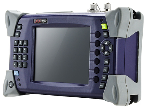
OTDR is short for optical time-domain reflectometer. It has gone through three stages of development. The first stage was in the 1980s. Optical fibers were just put into the market on a large scale. At that time, people still used the original way of fiber testing, and hand-held OTDR device or OTDR inspection technique were adopted to detect optical communication network. The second stage was from the late 1980s to the late 1990s. Fiber optics detection technology has been evolved to achieve real-time monitoring of optical network. The third stage is from the late 20th century to the early 21st century. OTDR has been combined with WDM (wavelength-division multiplexing) based on the advanced optical signal processing technology and all-optical communication devices.
To be specific, OTDR is an optoelectronic instrument used to characterize an optical fiber. It locates defects and faults, and determines the amount of signal loss at any point in an optical fiber. By injecting a series of optical pulses into the fiber, the light that is scattered or reflected will be back from points along the fiber at the same end. The scattered or reflected light that is gathered back is used to characterize the optical fiber. The strength of the return pulses is measured and integrated as a function of time, and plotted as a function of fiber length.
If you want to learn something about OTDR, these specifications are important for you to know:
Dynamic Range
The dynamic range of an OTDR determines the length of a fiber to be measured. The test pulse needs to be strong enough to get to the end of the fiber, and the sensor has to be good enough to measure the weakest backscatter signals which come from the end of a long fiber. Therefore, the pulse power of laser source and the sensitivity of sensor combine to decide whether the dynamic range is large or small. Sufficient dynamic range will produce a clear and smooth indication of the backscatter level at the far end of the fiber.
Dead Zone
Dead zone refers to the space on a fiber trace following a Fresnel reflection in which the high return level of the reflection covers up the lower level of backscatter. It is significant in determining the OTDR’s ability of detecting and measuring two closely spaced events on fiber links. Dead zone occurs in a fiber trace wherever there is a fiber connector. The space is directly related to the pulse width of the laser source. And high quality sensors recover quicker than cheaper ones to achieve shorter dead zones.
Resolution
OTDR includes two resolutions. One is loss resolution and the other is spatial resolution. Loss resolution is the ability of the sensor to distinguish the power levels it receives. Spatial resolution is how close the individual data points that make up a trace are spaced in time and corresponding distance.
Loss Accuracy
Loss accuracy of the OTDR sensor is measured in the same way as optical power meters and photodetectors. The accuracy depends on how closely the electrical current output corresponds to the input optical power.
Distance Accuracy
Clock stability, data point spacing and index of refraction (IOR) uncertainty are three components that may affect distance accuracy. Clock accuracy is stated as a percentage, which relates to percentage of distance measured. If the clock runs too fast or too slow, then the time measurements will be shorter or longer than the actual value. Also, if data point spacing is closer, data points are likely to fall closer to a fault in the fiber. Moreover, IOR is the ratio of the speed of light in a vacuum to the speed of light in a particular fiber. It is critical in accurate measurement of distance. If the IOR is wrong, then the distance will be wrong.
Applications
OTDR has been applied to various aspects of a fiber system. It is typically used to measure overall loss for system acceptance and commissioning, incoming inspection and verification of specifications on fiber reels. As for installation, construction and restoration, OTDR is deployed to measure splice loss in fusion and mechanical splices. When it comes to CATV, SONET and other analog or high-speed digital systems where reflections must be kept down, OTDR is used to measure reflectance or optical return loss of connectors and mechanical splices. Apart from these, it can also be applied to locate fiber breaks and defects, and detects the gradual or sudden degradation of fibers.
Conclusion
In other words, OTDR is a fiber optic tester for the characterization of optical networks that support telecommunications. It is applied to detect, locate, and measure elements at any location on a fiber optic link. And specifications like dynamic range, dead zone, resolution, loss and distance accuracy will influence the OTDR testing results. Thus, you should think twice before selecting an OTDR. Applications of what the instrument will be used for and the specifications of a suitable OTDR must be taken into consideration.
The article originates from http://www.chinacablesbuy.com/how-much-do-you-know-about-otdr.html.

没有评论:
发表评论