2016年7月29日星期五

Have You Chosen the Right Fiber Patch Panel?

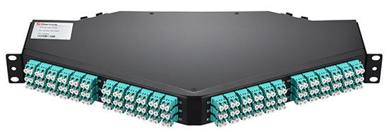
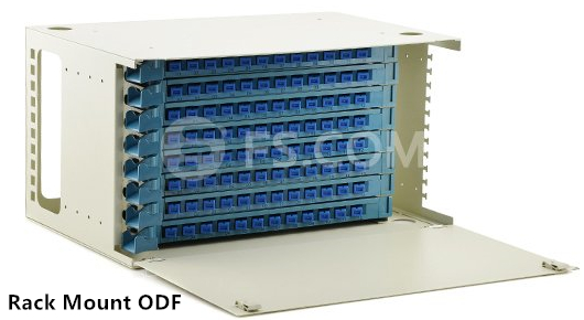
Fiber patch panel, namely fiber enclosure, is employed for better cable management and cable protection in data centers. With the help of fiber patch panels, it is more time-saving and easier for technicians to do the cabling work. Fiber patch panel terminates the fiber optic cables and provides access to the cables’ individual fibers for cross connection. In today’s market, there are various types of fiber patch panels. Choosing the right one for your network may seem a little complicated. This article will give several aspects that are important for selecting fiber patch panels.

Some Aspects for Consideration
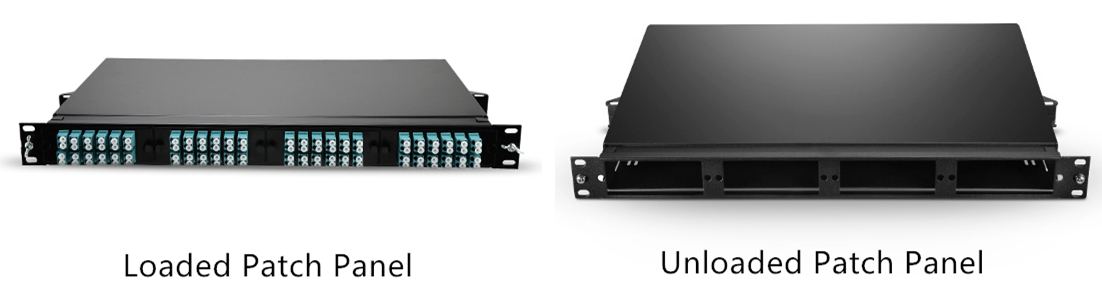
Loaded vs. Unloaded
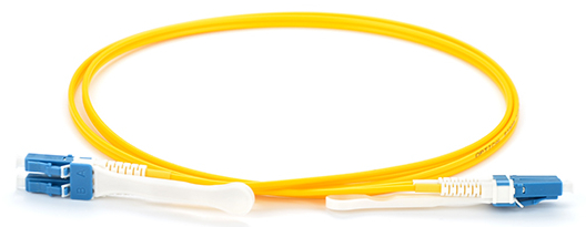
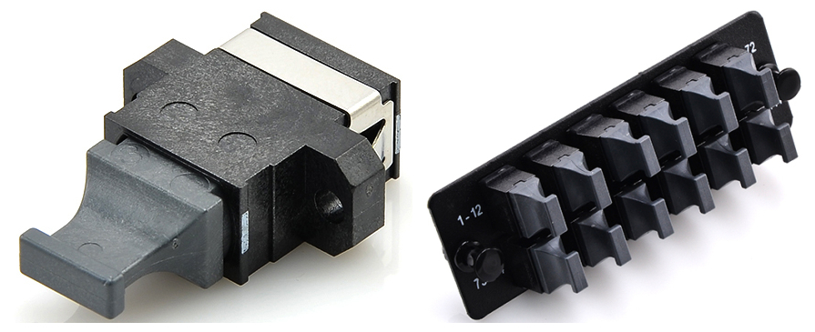
Loaded patch panel is pre-installed with adapter panels or cassettes while unloaded patch panel is empty with nothing inside. Typically, LC and MTP connectors are widely used in loaded patch panels. But these connectors in loaded panels are often permanently mounted, so if a port gets damaged it's dead forever. Unloaded patch panel, on the contrary, is more flexible that can let you swap out defective ports at will. But extra assemblies are demanded to be purchased and installed by yourself.
loaded-unloaded-patch-panel

Patch Panel Rack Size
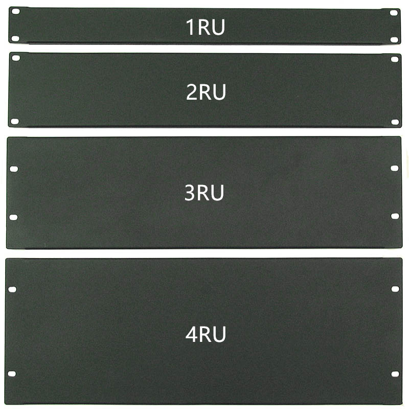
Fiber patch panel is usually measured by rack unit. A rack unit is used to describe the height of electronic equipment designed to mount in a 19-inch wide rack or a 23-inch wide rack. The height of rack-mounted equipment is frequently described as a number with U or RU. 1U refers to one rack unit, 2U refers to two rack units and so on. 2RU and 4RU are often used for high-density installations. So according to your application, the related rack size should also be adjusted.
patch-panel-rack-unit

Port Density
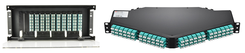
Port density is also an important part to be considered when purchasing fiber patch panels. As for normal patch panel, 1RU is able to carry 48 ports. If high-density patch panel is required, 1RU can support 96 ports. Moreover, 144 ports in 1RU is also available with ultra density patch panels. Since high-density has been frequently applied to the data centers, patch panels with higher port density becomes the future trend.

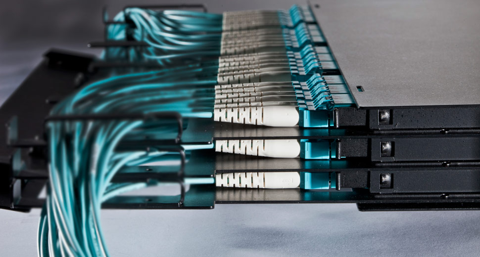
Migration to High-Density Patch Panels
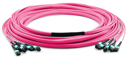
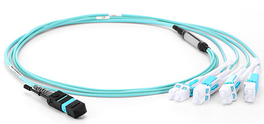
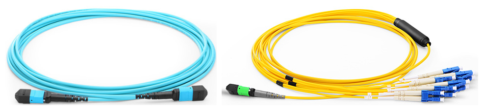
Nowadays, people are paying more attention to the 40G and 100G high speed networks. MPO/MTP breakout patch panel may be an ideal solution for this high-density installation. Deploying high-density patch panels has many advantages. It simplifies the cabling deployment by running a short fiber patch cable from your SAN or network switch up to the fiber patch panel. Much space can also be saved in data centers by mounting more cables into a smaller space. Installation is easier since no tools are required to install cassettes in the patch panels, and push-pull tabs are used to ease the difficulty of cable connections in the patch panels. After all, high-density patch panel is a cost-effective solution that overcomes the cabling congestion in high bandwidth networking.

high-density-fiber-patch-panel

Summary
The well-organized and well-protected cables are the guarantee of a stable network. Fiber patch panel is definitely the perfect solution that meets all the requirements. Choosing the right fiber patch panel is also beneficial to your network. You may consider from the aspects of loaded or unloaded types, rack size, port density, etc. In addition, high-density fiber patch panel is welcome by the 40G/100G network. If you want to achieve better high bandwidth application, patch panels with high-density ports are recommended.

2016年7月28日星期四

Guide to CWDM MUX/DEMUX System Installation

CWDM (coarse wavelength division multiplexing) comes from the WDM system. It is designed to increase the capacity of a fiber optic network without adding additional fiber. The wavelengths of CWDM channels are spaced 20 nm apart which allows the use of low-cost, uncooled lasers. The wavelengths usually range from 1270 nm to 1610 nm.

Today, CWDM Mux/Demux (multiplexer/demultiplexer) module is an important device to increase the current fiber cable capacity by transmitting multiple wavelengths with up to 18 signal channels over a single fiber. When using a CWDM multiplexer at the beginning of the network, accordingly a CWDM demultiplexer should be used at the opposite end to separate the wavelengths and direct them into the correct receivers. This greatly reduces the number of fiber cables and other data links.

CWDM-Mux-and-Demux

Basic Components of CWDM MUX/DEMUX System
Several basic components constitute a CWDM Mux/Demux system. They are a local unit, a remote unit, a rack-mount chassis, CWDM Mux/Demux modules, CWDM SFP transceivers and single-mode patch cables. The local unit and remote unit are two different switches. The rack-mount chassis is needed to be installed for holding the CWDM Mux/Demux module. As for the connections, CWDM SFP transceivers are usually used between a CWDM Mux/Demux module and a switch, and single-mode patch cables are used to connect transceivers to the module.

Preparation Before Installation
Multiple single-mode patch cables are needed for CWDM Mux/Demux system connection. And the transceivers used in the system must support the wavelengths from 1270 nm to 1610 nm. Make sure the installation environment is in a dry and interior space. The module should have enough room to create airflow for easier heat distribution. Any inappropriate arrangement that obstructs the ventilation holes should also be avoided.

CWDM MUX/DEMUX System Installation
Step one, mount the system chassis on the rack. The CWDM rack-mount chassis can be mounted in a standard 19-inch cabinet or rack. Make sure that you install the rack-mount chassis in the same rack or an adjacent rack to your system so that you can connect all the cables between your CWDM Mux/Demux modules and the CWDM SFP transceivers.

mounting-system-chassis

Step two, install the CWDM Mux/Demux modules. You should first loose the captive screws on the blank of module panel and remove the panel. Then align the module with the slot of the chassis shelf and gently push the module into the slot. Finally, ensure that you line up the captive screws on the module with the screw holes on the shelf and tighten them up.

installing-CWDM-MuxDemux-modules

Step three, install CWDM SFP transceivers. Since each channel has a specific wavelength, transceivers must comply with the right wavelengths. Each wavelength must not appear more than once in the system. Device pairs must carry transceivers with the same wavelength.

CWDM-SFP-transceiver

Step four, install the CWDM Mux/Demux to the switch. After inserting the CWDM SFP transceiver into the switch, single-mode patch cables are used to connect the transceiver to the CWDM Mux/Demux module.

Step five, connect the CWDM MUX/DEMUX pairs. In a CWDM MUX/DEMUX system, multiplexer and demultiplexer must be installed in pairs. Two strands of single-mode patch cables are needed in the duplex Mux/Demux module, and one strand of single-mode patch cable is enough for the simplex Mux/Demux module.
When you finish all these steps, the installation of CWDM Mux/Demux system is successfully completed.

Conclusion
CWDM Mux/Demux system is definitely a good solution to high capacity data transmission. It is efficient for power, space and cost saving. And the installation procedure is easy to follow. All the components above are available in FS.COM. If you are interested, please come and visit our website for more information.

2016年7月27日星期三

Suggestions for High-Density Cable Management

People who work in data centers are familiar with cable management. Terrible cable management destroys the stability and availability of networking, especially for high-density applications. Since the advancement of technology brings us to a higher broadband network, high-density components are widely applied to data infrastructures. The importance of high-density cable management should be valued.

Useful High-Density Components
Using the right devices for high-density connections will ease the difficulty of cable management. High-density patch panels, high-density TAB patch cables and high-density trunk cables are recommended for high-density installations.

High-density patch panels provide fast, intuitive and easy deployment of high-density interconnects and cross-connects in data centers. They also conserve valuable rack space. Compared to standard patch panels, angled styles can facilitate cable management practices. Omitting the necessity of buying new components, reconfigurable panels with various mounting and attachment features can ensure that patch panels are fit for your data center configuration. For instance, the following picture shows an ultra high-density angled patch panel with 144 ports highly welcomed by high-density network application.

high-density-patch-panels

High-density cabling has been increased because of the deployment of higher network speeds. Installing cables with smaller overall diameter into dense patch cord trays can save lots of space to improve cable management. These high-density patch cables also provide better airflow to maintain consistent operating temperatures, reducing the likelihood of failure or downtime. Finger access to each patch cable becomes more difficult as cable density increases. To ensure easy access, looking for high-density patch cords that are easy to remove is important. Thus, the patch cable using a flexible pull-tab efficiently solves the issue. These tabs can help increase cabling density and maintain reliability, preventing you from accidentally loosening surrounding connectors as you access the patch cable you need. The picture below is a typical HD TAB fiber patch cable.

high-density-patch-cable

High-density trunks allow tighter trunk cable bends for slack storage and routing. Less space is consumed and installation is easier when using high-density trunks that offer smaller transitions. Cable pulling and cable management are improved when a cable with a smaller overall diameter is used. High-density trunks should also be marked for fast fiber type identification.

high-density-trunks

Things to Avoid During Installation & Daily Practices
Point one, avoid over-bundling the cables or placing multiple bundles on top of each other, which can degrade performance of the cables underneath. Additionally, keep fiber and copper runs separated. The weight of the copper cables can crush fiber cables that are placed underneath.

Point two, avoid routing cables through pipes and holes. This may limit additional future cable runs.

Point three, avoid mounting cabling components in locations that block access to other equipment inside and outside the racks. For example, blocking the cooling fans will restrict airflow.

Point four, avoid leaving loose cables on the floor; this is a major safety hazard. Use the horizontal, vertical, or overhead cable managers.

Point five, avoid exposing cables to direct sunlight and areas of condensation.

Point six, avoid mixing different cable types within a bundled group.

Summary
In conclusion, a good cable management of high-density devices is very essential to extend their service life. Choose the right components will also facilitate the efficiency of cable management. There is no perfect solution for all your cable management demands. Some suggestions may help you to a certain degree, but you should still arrange your equipment according to the actual environment.

2016年7月21日星期四

Applications of Special-Purpose Fiber Patch Cables

Fiber patch cable is an indispensable part for fiber optic communication. Signals are depending on this device to finish data transmission. Standard fiber patch cables are the most common patch cables in the market. However, there are some specific applications that need special treatment. Therefore, a range of special-purpose fiber patch cables have emerged as required. This article will recommend several unique but useful fiber patch cables. Maybe one of them will suit your needs.

HD TAB Fiber Patch Cable
As the name suggests, HD TAB fiber patch cable has a special push-pull tab which provides great convenience for high-density installations. Technicians can have easier finger access to installing or releasing the cables without using any additional tools. In today’s market, HD TAB fiber patch cables are usually terminated with LC or MTP/MPO connectors. If you are seeking for a high-density and space-saving solution, HD TAB fiber patch cable is highly recommended.
HD-TAB-fiber-patch-cable

The uniboot LC fiber patch cable bundles two fibers in a single patch cord which saves much space for cabling. The changing of its LC uniboot connector polarity is easy ,which skips the using of tools. Uniboot LC fiber patch cable is available in different fiber types of single-mode, OM3 and OM4. The purpose of this cable is to deliver maximum connectivity performance in a minimal footprint. If you want to achieve an easier cable management, this is definitely a good choice.

In addition, there is an upgraded version of uniboot LC fiber patch cable - HD uniboot LC fiber patch cable. You can’t miss this one if you are looking for the extreme space saving solution. It is basically the combination of uniboot LC fiber patch cable and HD TAB fiber patch cable. Likewise, two optical fibers are wrapped together in a single strand. The difference is that its connector is attached with a push-pull tab which is more flexible for releasing the connector. It can be applied to data centers and high-density environments.
uniboot-LC-fiber-patch-cable

In terms of data security, keyed LC fiber patch cable or secured LC fiber patch cable is the perfect solution. It is designed to prevent unauthorized and inadvertent changes in highly sensitive applications. Keyed LC fiber patch cable is identified by the connector color. Each color of a set of keyed LC connectivity products represents a unique keying pattern that only allows matched color mating. Multiple keyed LC connectivity products are included in this family. The picture below gives an example of the simplex keyed LC connectivity.
keyed-lc-connector-and-adapter

Originally, when bending an optical fiber by stress, there will be a bend loss. This sensitive nature of optical fiber causes low efficiency in optical transmission. But it is hard to deal with the problem as bend loss issue is difficult to locate. Fortunately, bend insensitive fiber patch cable is designed to solve this problem. In this kind of cable, a layer of glass is added around the core of the fiber which has a lower index of refraction that literally "reflects" the weakly guided modes back into the core. Many data centers and FTTH systems are deploying this cable to reach lower signal loss.

Conclusion
From this article, we can see that there still exists many other types of fiber patch cables. And special fiber optic cable solutions are always more effective to special applications. By the way, if you just want a standard optical cable, you may consider from the aspects of fiber type, connector type, connector polishing type, fiber count, cable jacket, etc. These options are fit for average circumstances when choosing the optical cables. Hope you choose the right one according to your requirements!

2016年7月20日星期三

Optical Transport Network (OTN) for High Speed Service

Nowadays, the SONET/SDH network is an universal network that combines with WDM (wavelength division multiplexing) technique to transmit multiple optical signals over a single fiber. In future networking, high speed transmission is no doubt the migration trend. Inspired by the SONET/SDH network, ITU-T (ITU Telecommunication Standardization Sector) has defined the optical transport network (OTN) to achieve a more cost-effective high speed network with the help of WDM technology.

Generally speaking, OTN is a network interface protocol put forward in ITU G.709. OTN adds OAM (operations, administration and maintenance) functionality to optical carriers. It allows network operators to converge networks through seamless transport of the numerous types of legacy protocols, while providing the flexibility required to support future client protocols. Unlike the previous SONET/SDH, OTN is a fully transparent network that provides support for optical networking on a WDM basis. Since multiple data frames have been wrapped together into a single entity in OTN, it is also known as the "digital wrapper".

Working Principle of OTN
You may wonder how OTN works in practice. Actually, its working structure and format very resemble the SONET/SDH network. Six layers are included in the OTN network: OPU (optical payload unit), ODU (optical data unit), OTU (optical transport unit), OCh (optical channel), OMS (optical multiplex section) and OTS (optical transport section).

OPU, ODU and OTU are the three overhead areas of OTN frame. OPU is similar to the "path" layer of SONET/SDH, which provides information on the type of signal mapped into the payload and the mapping structure. ODU resembles the "line overhead" layer of SONET/SDH, which adds the optical path-level monitoring, alarm indication signals, automatic protection switching bytes and embedded data communications channels. OTU is like the "section overhead" in SONET/SDH, and it represents a physical optical port that adds performance monitoring and FEC (forward error correction). OCh is for the conversion of electrical signal to optical signal and modulates the DWDM wavelength carrier. OMS multiplexes several wavelengths in the section between OADMs (optical add drop multiplexer). OTS manages the fixed DWDM wavelengths between each of the in-line optical amplifier units.
OTN-structure

Advantages of OTN
There are many advantages of OTN. Firstly, it separates the network against uncertain service by providing transparent native transport of signals encapsulating all client-management information. Secondly, it performs multiplexing for optimum capacity utilization which enhances network efficiency. Thirdly, it improves maintenance capability for signals transmitting through multi-operator networks by providing multi-layer performance monitoring.

Migration to High Speed OTN
With the fast evolution of networking, OTN standard is able to reach a higher speed service. Its multiplexing hierarchy allows any OTN switch and any WDM platform to electronically groom and switch lower-rate services within 10 Gbps, 40 Gbps, or even 100 Gbps wavelengths. This eliminates the need for external wavelength demultiplexing and manual interconnects. OTN network is definitely the best solution for future high speed networking over long distance. The picture below shows the OTN mapping diagram for high speed transmission.
OTN-high-speed-mapping-diagram


Conclusion
Over the years, OTN has never stopped improving itself. Driven by the needs for high speed transmission, OTN combined with WDM is obviously a better choice in networking. It is a cost-effective way to build an optical transport network accommodating high throughput broadband services. I believe more and more people will employ this standard in their own network in the near future.

2016年7月19日星期二

Fiber Termination Box - Solution for FTTH Network

In the FTTH network, cable management is a real task. In order to transmit signals to multiple terminations, large amount of optical pigtails are used in the cabling system. A solution must be found to solve the problem of cable routing. Luckily, the advent of fiber termination box has efficiently handled the crux by accommodating and protecting the fiber cables.

Specifically, fiber termination box (FTB), namely optical termination box (OTB), is a kind of fiber optic management product used to distribute and protect the optical fiber links in FTTH Network. Owing to its compact and small size, it is also considered to be the mini version of fiber optic patch panel or optical distribution frame (ODF). The number of ports in fiber termination box is varied from 8 ports to 96 ports, you may choose the right box according to your cable needs.

Fiber Termination Box Types
  • Wall Mount vs. Rack Mount
In terms of different designs, fiber termination box can be classified into wall mount and rack mount types. Wall mount fiber termination box is a perfect solution to be used in building entrance terminals, telecommunication closets, main cross-connects, computer rooms and other controlled environments. It is a suitable device for pre-connectorized cables, field installation of connectors and field splicing of pigtails.
wall-mount-FTB

Rack mount fiber termination box is designed for cross-connect and interconnect architecture which has interfaces between outside plant cables and transmission equipment. And the box unit provides space for fiber splicing, distribution, termination, patching, storage and management.
rack-mount-FTB

  • Indoor vs. Outdoor
With regard to wall mount fiber termination box, it has another two classifications of indoor and outdoor types. Obviously, this is categorized according to the installation site. As the transition point between the riser and the horizontal cable, indoor wall mount fiber termination box offers the operator with optimal flexibility. It serves as the storage place for extended and terminated fibers or as the splice point for spliced fibers.
indoor-wall-mount-FTB

Outdoor wall mount fiber termination box is also used for fiber splicing, termination, and cable management. But its enclosure is usually sealed to prevent cables from environmental damages in FTTH network.
outdoor-wall-mount-FTB

Applications
Fiber termination box is typically applied to telecom equipment room or network equipment room. It is also available for the distribution and termination connection for various kinds of fiber optic systems, and is especially suitable for mini-network terminal distribution in which the optical cables, patch cores or pigtails are connected.

Distinctions Between Fiber Termination Box and Fiber Splice Tray
Sometimes, people may mix the fiber termination box with fiber splice tray due to the similar inside structure. Besides other applications, fiber termination box is often used as the terminal junction where a single cable is spliced into multiple optical pigtails that have connectors at one end and no connector at the other end. Sometimes, fiber splice tray is inside the fiber termination box to contain the spliced fibers. But it can also be employed for independent use to protect the spliced fibers. Thus, these two devices are not interchangeable.

Conclusion
In conclusion, fiber termination box is an important device used for protecting and distributing optical fiber links. The utilization of fiber termination box greatly eases the stress of cable management in FTTH network. Wall mount both indoor and outdoor FTBs and rack mount FTBs are widely deployed for optical communication infrastructures. Of course, a right selection will also contribute to your network.

2016年7月16日星期六

How to Choose Optical Distribution Frame

Due to the development of high speed transmission, demands for high density patching have increased in recent years. However, the management of installed cables still remains a difficult task. To achieve a simpler way of cable organization, people often use the cost-effective optical distribution frames (ODF) to arrange optical cable connections. ODF plays an important part in building a safe and flexible operation environment for optical network. Different kinds of ODFs are provided in the market, but you need to choose the right one according to actual situation.

Functions of ODF
ODF is mainly used for fiber optic terminal splicing, fiber optic connector installation, optical path adjusting, excess pigtail storage and fiber optic cable protection. When cable enters into the rack, ODF should mechanically fix the cable and install the ground wire protection. Fiber optic cables will also be divided into groups for better management. When it comes to the spliced fibers, extra parts will be stored as a coil and the fusion splices are well-protected in the ODF. Adapters and connectors are pluggable and optical path can be freely adjusted or tested. Moreover, enough space of ODF is provided to satisfy a clear connection.

Things to Consider for Choosing ODF
Selecting a right ODF is vital to future applications. Here are some recommended aspects for you to consider before purchasing:

1) ODF Types
Generally, there are three types in terms of its structure. They are wall mount ODF, floor mount ODF and rack mount ODF. Wall mount ODF shapes are like a small box installed on the wall. Because the space is restrained, wall mount ODF only accepts small fiber counts. Floor mount ODF has a fixed and large fiber capacity in a closed structure. Rack mount ODF is more flexible to be installed on the rack to meet your requirements for different cable counts and specifications. This type is frequently used in optical distribution system with 19 inches’ specification to accommodate the size of standard transmission rack.
rack-mount-ODF

2) Fiber Counts
High density fiber counts have become the trend for future data center. Today, a single ODF unit usually has 12, 24, 36, 48, 72, 96 or even 144 ports. Customized ODF according to your needs is also available in the market.

3) Easy Management
Using a high density device will definitely increase the difficulty of cable management. ODF should allow for easy access to the connectors on the front and rear ports for quick insertion and removal, which means that ODF must provide adequate space. Besides, ODF should have the right colored adapters to match with optical connectors in case of wrong connections.

4) Good Protection
One basic function of ODF is the protection function. A standard ODF should comprise protection devices to prevent fiber optic connections from dust or stress damages. For instance, the splicing connection is very sensitive to outside environment and is important to the normal operation of a network, so the good quality of ODF protection device is of great importance.

Conclusion
In a word, ODF is now an indispensable equipment for the deployment of optical network. High-density ODF is especially popular in the industry. To find a suitable ODF with a lower price, careful selection is important. This article only provides some basic factors that may affect the application of ODF. For more information, please visit FS.COM.

2016年7月15日星期五

MTP/MPO - An Easier Solution for High Density Patching

With the continuing growth of data throughput in networking, 40G network now becomes the commonplace and 100G has also been used increasing widespread. To achieve a higher transmission data rate, it is important to find a suitable solution for the high density cable routing. Thus, the arrival of MTP/MPO connection standard is a piece of good news for high density patching. The MTP/MPO technology is available with multi-fiber connectors which is a perfect solution for high-performance data transmission. There are a lot of benefits when adopting the MTP/MPO structure. This article will provide some effective MTP/MPO assemblies that are frequently used to meet high density demands.

Superiority of MPO/MTP Assemblies
Actual practice proves that MPO/MTP components are superior to other assemblies in high density applications. They can connect to equipment with various date rates of 10 Gbps, 40 Gbps or 100 Gbps, which makes them more flexible for the devices. Also, their installation is very simple. No tools are required to install the cassette in the panel enclosure, and the push-pull connection offers an easier way to be locked or unlocked in patch panels. Owing to the modular cassette system, they are also pretty adjustable in network reconfiguration. You may think this must cost you a great deal, however, the initial investment is very cost-effective.

Recommended MPO/MTP Products

Here are some recommended MPO/MTP products for high density patching. Using these assemblies can achieve a significant progress in operations.

1) MTP/MPO Cables
MTP/MPO cables consist of MTP/MPO connectors and fiber cables. Sometimes, other types of connector can also be linked to one termination. The fiber cables are usually employing OM3 or OM4 laser optimized multimode optical fibers. MTP/MPO trunk cables, harness/breakout cables and direct pigtails are three categories of MTP/MPO cables. The MTP/MPO trunk cables are available with 8, 12, 24, 36, 48, 72 and 144 fibers for single-mode and multimode applications. The harness/breakout cables is designed to work from trunk backbone assemblies to fiber rack system in the high density cabling. One end is terminated with a MTP/MPO connector, and the other end can have other options of connectors such as LC/SC/ST/MTRJ. The MTP/MPO pigtail cables are typically used for splicing directly inside fiber management panels near adapter ends.

mtp-mpo-cable

Appropriate utilization of MTP/MPO cassettes can help reduce installation time and investment for an optical network infrastructure in the premises. Rapid deployment of high density data center infrastructure can also be realized thanks to the modular system. The MTP/MPO plug-n-play cassette provides the interconnection between MTP/MPO backbones with LC/SC/ST/FC patching. Other recommended cassettes are 1U 19” rack mount cassettes holders, 4U 19” rack mount cassettes holders and 144 ports ultra HD angled patch panel. 1U 19” rack mount enclosure is integrated with three pieces of plug-n-play cassettes for up to 72 fibers patching. 4U 19” rack mount enclosure has 12 plug-n-play cassette pieces with 288 fibers patching. 144 ports ultra high density cassette is equipped with 72 LC duplex adapters for 144 fibers patching.

mtp-mpo-cassettes

3) MTP/MPO Optical Adapter & Adapter Panels
The black colored MTP/MPO adapter has two types as key-up to key-down and key-up to key-up. It provides the connection between cable to cable or cable to equipment in the MTP/MPO style. The MTP/MPO fiber adapter panels are available with 2, 3, 4, 6, 8, 12, 16 and 18 ports both horizontally and vertically in lighter package.

mtp-mpo-optcial-adapter-and-adapter-panels

Conclusion
In summary, if you need devices for high density deployment, MTP/MPO assemblies are absolutely best solutions. Applying the MTP/MPO connection, its patch cables, cassettes and adapters will be promoted to a more effective use.

Effective CWDM & DWDM Mux/Demux Solutions for WDM System

Wavelength division multiplexing (WDM) system is designed for high capacity communications. It is now frequently used as a method to merge multiple optical signals with different wavelengths onto a single fiber. There are two divisions of WDM system: coarse wavelength division multiplexing (CWDM) and dense wavelength division multiplexing (DWDM). Using WDM can enhance the effectiveness of bandwidth in fiber optic communications. The WDM Mux/Demux has a number of communication channels, and matches with a certain frequency. Wavelengths are separated to different receivers at the destination. Mux/Demux module is an important assembly using WDM technology. This article will introduce some effective CWDM and DWDM Mux/Demux solutions for WDM system.

CWDM Mux/Demux & DWDM Mux/Demux

CWDM Mux/Demux
CWDM Mux/Demux is a flexible network solution for WDM optical networks. At most 18 full-duplex wavelengths can be added over a single fiber trunk which greatly alleviates fiber exhaustion. With low insertion loss and high stability, CWDM Mux/Demux is applied to many operations, such as CATV links, WDM systems, test and measurement, metro and access networks, FTTH networks, etc. The deployment of CWDM Mux/Demux is transparent and clear. Its compact form factor enables a much easier manipulation. Only coarse wavelengths can be transmitted over the fiber which reduces the WDM system cost.

Three kinds of CWDM Mux/Demux are widely used in the application. They are 1RU 19" rack chassis CWDM Mux/Demux, half 19"/1RU CWDM Mux/Demux and splice/pigtailed CWDM Mux/Demux. CWDM Mux/Demux in 19 inch rack mount package is often used for CWDM, EPON and CATV network. Half 19"/1RU CWDM Mux/Demux is packed in LGX box using thing film coating and non-flux metal bonding micro optics packaging. Splice/pigtailed CWDM Mux/Demux is packed in the ABS box package based on standard thin film filter (TFF) technology.

DWDM Mux/Demux
DWDM Mux/Demux conveys optical signals in a more dense wavelength. It is especially used for long distance transmission where wavelengths are highly-packed together. The maximum delivered wavelengths can reach up to 48 channels in 100GHz grid (0.8nm) and 96 channels in 50GHz grid (0.4nm). DWDM Mux/Demux uses a reliable passive WDM technology that achieves low insertion loss. And it provides a solution for adding WDM technology to any existing network device. Applications like point-to-point DWDM fiber optimization, linear add/drop DWDM fiber optimization, external optical monitoring are typically using DWDM Mux/Demux module.

Likewise, 1RU 19" rack chassis DWDM Mux/Demux, Half 19"/1RU DWDM Mux/Demux and splice/pigtailed DWDM Mux/Demux are three divisions of DWDM Mux/Demux modules. The first type is in 19 inch rack mount package used for long-haul transmission over C-band range of wavelengths. The second one is in LGX package used for PDH, SDH/SONET, Ethernet services transmission. The last one is in ABS box package and its pigtails are labeled with wavelengths.

Effective CWDM Mux/Demux & DWDM Mux/Demux Solutions

18-CH CWDM Mux/Demux is a highly recommended 1RU rack-mount CWDM Mux/Demux that combines 18 CWDM sources on a single fiber. The insertion loss is below 4.9 dB. Moreover, it has a monitor port that enables maintenance without ceasing the operation.
18ch-cwdm-mux-demux

40-CH DWDM Mux/Demux has 40 channels. As a DWDM Mux/Demux module with high density, low-loss and independent 1RU rack mount package, the best utilization of this device is to employ it for high density applications over long-haul transmission. It multiplexes and demultiplexes 40 DWDM wavelengths with 100 GHz in a ring or point-point network. It is a highly cost-effective DWDM Mux/Demux module.
40ch-dwdm-mux-demux

Conclusion
To improve the efficiency of network transmission, WDM technology is often deployed in the devices. 18-CH CWDM Mux/Demux and 40-CH DWDM Mux/Demux are now recommended as the most cost-effective WDM solutions with expanded fiber capabilities. Hope you can choose and use them wisely.

2016年7月9日星期六

OADM - Optical Add-Drop Multiplexer

With the development of optical communication technologies, people are entering into the new era of information. In order to overcome the data rate limitation of traditional communication system, WDM and OTDM technologies are typically used to increase fiber optic bandwidth. However, no matter which kind of technology is adopted to construct fiber optic network, optical add-drop multiplexer (OADM) technology is needed in the system. It makes the fiber optic network more flexible, optional and transparent. OADM is now a key component of the all-optical network to enhance the network reliability and efficiency. This article will give a brief introduction about the basic knowledge of OADM.

OADM

Definition of OADM
So what is an optical add-drop multiplexer or OADM? To be specific, an OADM is a device used in wavelength-division multiplexing systems for multiplexing and routing different channels of light into or out of a single-mode fiber. “Add” refers to the capability of the device to add one or more new wavelength channels to an existing multi-wavelength WDM signal. On the contrary, “drop” refers to its ability of removing one or more channels and passing those signals to another network path.

There are three parts of a traditional OADM - an optical demultiplexer, an optical multiplexer and a reconfiguration method between the demultiplexer and the multiplexer. The demultiplexer separates wavelengths from an input fiber onto different ports. The multiplexer multiplexes the wavelength channels that come from demultiplexer ports with those from the add ports onto a single output fiber. The reconfiguration can be achieved by a fiber patch panel or by optical switches which direct the wavelengths to the multiplexer or to drop ports.

Operating Principle of OADM
The WDM signal contains multiple wavelength channels. When these wavelengths enter into the main input of OADM, they can be selected to enter the drop output ports according to your application requirements. Correspondingly, the add ports will input the required wavelength channels. And those irrelevant wavelengths will directly pass through OADM and then be multiplexed with the added wavelengths together leaving the main output. Therefore, the function of OADM is to download necessary local signals and upload signals for the user of next node.

OADM-operating-principle

Two Kinds of OADM
Fixed OADM and reconfigurable OADM are two commonly used types of OADM. The former is used to drop or add data signals on dedicated WDM channels, and the latter is used to electronically alter the selected channel routing through the optical network.

Fixed OADM or FOADM is the traditional construction of OADM. It uses a filter to select a dropping wavelength and a multiplexer to add a new channel at the same wavelength. Different from FOADM, reconfigurable OADM or ROADM is a dynamic type which has the ability to remotely switch traffic from a WDM system at the wavelength layer. It provides flexibility in rerouting optical streams, avoids faculty connections, and allows minimal service disruption and the ability to adapt or upgrade the optical network to different WDM technologies.

Conclusion
OADM is an important element of an optical fiber network. It can be both deployed for long-haul core networks or short metro networks. Fixed OADM and reconfiguration OADM are two commonly used types. A further development of OADM is absolutely the future trend in fiber optic communications.

Guide to Optical Amplifier

Optical amplifier is an significant device deployed for optical communication and laser physics. No need for converting optical signals into electrical signals first, optical amplifier can directly amplify the optical signals. It is considered to be a laser without optical cavity or with suppressed feedback from cavity. Optical amplifiers are often installed at places where optical signals are weak and need to be enhanced. This ensures the stable transmission of optical signals in the rest cables. Thus, we should attach greater importance to optical amplifier. And this article will guide you to know the secrets of optical amplifier.


optical-amplifier

Functions of Optical Amplifier
In an optical network, optical amplifiers can be used as booster amplifiers, pre-amplifiers or inline amplifiers. These functions are a little different from each other. When a optical amplifier acts as a booster, it is used to amplify the signals that leave the transmitter into the required level before entering into fiber links. The booster amplifier is especially important to a WDM link as the multiplexer attenuates optical signals. Pre-amplifier is used at the other end of a link to amplify the signal level for it to be detected over or above the thermal noise of the receiver. As for inline amplifier, it is used for links over 150 km in case signals become weak in long distance. Every 80 to 100 km, inline amplifier will be placed to make sure that the signal level is over the noise floor.

optical-amplifier-function

Three Types of Optical Amplifiers
1) Erbium Doped Fiber Amplifier (EDFA)
Erbium doped fiber amplifier or EDFA is now the most widely used optical amplifier for long range fiber communications. Its optical fiber (usually a single-mode fiber) at the core is doped with rare earth element erbium to absorb light at one frequency and emit light at another frequency. The light is pumped from laser diodes with a wavelength around 980 nm and sometimes around 1480 nm. EDFA has advantages of high gain, wide bandwidth, high output power, high pumping efficiency, low insertion loss and insensitive to polarization state which turns out to be a good solution for DWDM, CATV and SDH applications.

2) Roman Amplifier
Roman amplifier is designed based on the Roman gain which results from the effect of stimulated Roman scattering. When a lower frequency signal photon induces the inelastic scattering of a higher-frequency pump photon in an optical medium in the nonlinear regime, another signal photon is produced with the surplus energy resonantly passed to the vibrational states of the medium. Roman amplifier is often installed in the mid-stream of a signal or in front of the receiver to amplify signal levels. It has the advantages of greater operating wavelength range, constant optical gain and effective noise figure reduction.

3) Semiconductor Optical Amplifier (SOA)
Semiconductor optical amplifier or SOA is the optical amplifier based on a semiconductor gain medium. Light is sent through a semiconductor single-mode waveguide with transverse dimensions. SOA is usually connected to the output of 1310nm transceivers to amplify signal level before entering into optical fiber. It supports all format of 1310nm wavelength signals and is compatible with all data rates. Thus, SOA is an ideal solution for DWDM network optical amplification.

Conclusion
To sum up, optical amplifier enables the optical transmission over long distance by amplifying signals. This article introduces the fundamentals of its functions and some commonly used types. You may have an overall understanding about optical amplifier. For more information, please visit FS.COM.

What is Fiber Optic Isolator?

Fiber optic isolator is a passive component used for fiber optic communications. As a magneto-optic device, the purpose of optical isolator is to allow light to be transmitted in only one direction. This helps prevent laser source from unwanted feedback which will damage the laser source or arouse unexpected laser problems, such as mode hop, amplitude modulate, frequency shift and so on. Therefore, isolator is an useful and indispensable device to reduce these effects. In the following parts, fiber optic isolator’s construction, operating principle and classifications will be discussed.

optical-isolator

Construction of Optical Isolator
Fiber optic isolator includes three main parts of an input polarizer, a Faraday rotator with magnet, and an output polarizer. Only linearly polarized light can pass through the input polarizer into the Faraday rotator. The function of the Faraday rotator is to rotate the input light by a certain angle before it reaches the output polarizer. This allows the light in the forward direction to pass unimpeded. However, the light in the reverse direction will not be able to pass the optical isolator and is either reflected or absorbed. These three components of optical isolator skillfully work together and ensure the normal transmission of light signals.

Operation of Optical Isolator
The operation of optical isolator is based on the Faraday effect which was discovered by Michael Faraday in 1842. Faraday effect refers to a phenomenon that the plane of polarized light rotates while transmitting through glass (or other materials) that is exposed to a magnetic field. The rotation direction depends on the direction of the magnetic field instead of the direction of light transmission.

According to different light directions, there are two types of operation modes. One is the forward mode and the other is the backward mode. The forward mode enables light enter into the input polarizer and become linearly polarized. When laser light reaches the Faraday rotator, the Faraday rotator rod will rotate by 45° polarization. Thus, the light finally leaves the output polarizer at 45° polarization. However in the backward mode, the light first enters into the output polarizer with a 45° polarization. Next, as it passes through the Faraday rotator, it continues to be rotated for anther 45° in the same direction. Then the light of 90° polarization becomes vertical to the input polarizer and can not leave the isolator. As a result, the light will be either reflected or absorbed.

optical-isolator-operation

Types of Optical Isolator
1) Polarized Optical Isolator
Polarized optical isolator employs the polarization axis to keep light transmit in one direction. It allows light to propagate forward freely, but disallows any light to travel back. Also, there are dependent and independent polarized optical isolators. The latter is more complicated and often used in EDFA optical amplifier.

2) Composite Optical Isolator
Composite optical isolator is actually a type of independent polarized optical isolator. It is used in EDFA optical amplifier which consists of many other components, such as erbium-doped fiber, wavelength-division multiplexer, pumping diode laser and so on. Since there are many other components in EDFA module, this type of isolator is named as composite optical isolator.

3) Magnetic Optical Isolator
Magnetic optical isolator is essentially the polarized optical isolator in another expression. It stresses the magnetic part of a Faraday rotator. The Faraday rotator is generally a rod made of a magnetic crystal under strong magnetic field with Faraday effect.

Conclusion
In summary, fiber optic isolator guarantees the stable function of laser transmitter and amplifiers by eliminating unnecessary lights. It also ensures a higher performance of light transmission. Using fiber optic isolator is no doubt a good choice for your network.

2016年7月1日星期五

Introduction to Simplex, Half Duplex and Full Duplex

Simplex, half duplex and full duplex are three kinds of communication channels in telecommunications and computer networking. These communication channels provide pathways to convey information. A communication channel can be either a physical transmission medium or a logical connection over a multiplexed medium. The physical transmission medium refers to the material substance that can propagate energy waves, such as wires in data communication. And the logical connection usually refers to the circuit switched connection or packet-mode virtual circuit connection, such as a radio channel. Thanks to the help of communication channels, information can be transmitted without obstruction. A brief introduction about three communication channel types will be given in this article.

Three Types of Communication Channel
1) Simplex
A simplex communication channel only sends information in one direction. For example, a radio station usually sends signals to the audience but never receives signals from them, thus a radio station is a simplex channel. It is also common to use simplex channel in fiber optic communication. One strand is used for transmitting signals and the other is for receiving signals. But this might not be obvious because the pair of fiber strands are often combined to one cable. The good part of simplex mode is that its entire bandwidth can be used during the transmission.

Simplex

2) Half duplex
In half duplex mode, data can be transmitted in both directions on a signal carrier except not at the same time. At a certain point, it is actually a simplex channel whose transmission direction can be switched. Walkie-talkie is a typical half duplex device. It has a “push-to-talk” button which can be used to turn on the transmitter but turn off the receiver. Therefore, once you push the button, you cannot hear the person you are talking to but your partner can hear you. An advantage of half-duplex is that the single track is cheaper than the double tracks.

Half-Duplex

3) Full duplex
A full duplex communication channel is able to transmit data in both directions on a signal carrier at the same time. It is constructed as a pair of simplex links that allows bidirectional simultaneous transmission. Take telephone as an example, people at both ends of a call can speak and be heard by each other at the same time because there are two communication paths between them. Thus, using the full duplex mode can greatly increase the efficiency of communication.

Full-Duplex

A simplex fiber optic cable has only one tight-buffered fiber inside cable jacket for one-way data transmission. The aramid yarn and protective jacket enable the cable to be connected and crimped to a mechanical connector. It can be used for both single-mode and multimode fiber optic cables. For instance, single-mode simplex fiber optic cable is suitable for networks that require data to be transmitted in one direction over long distance.

Different from simplex fiber optic cable, the duplex one has two fibers constructed in a zipcord style. It is often used for duplex communication between devices to transmit and receive signals simultaneously. The duplex fiber optic cable is required for all sorts of applications, such as workstations, fiber switches and servers, fiber modems and so on. And single-mode or multimode cable is also available with duplex cables.

Conclusion
The concept of communication channel is important for understanding the operation of networking. Simplex, half duplex and full duplex are three modes of communication channels. Each of them can be deployed for different applications. It is more cost-effective to choose the right fiber optic cable according to its channel mode.