2017年1月17日星期二

Have You Chosen the Right Power Cord?

Different cables have particular applications. Some are used for data transmission like fiber optic cable or copper cable, and some are used for the transmission of electrical power. Power cord is the assembly widely used as the connection between main electricity supply and the device through a wall socket or extension cord. Power cord is adopted in almost every where when the alternating current power is required. However, have you chosen the right type of power cord for your device? From this article, you may find the answers.
power cord

Overview of Power Cord
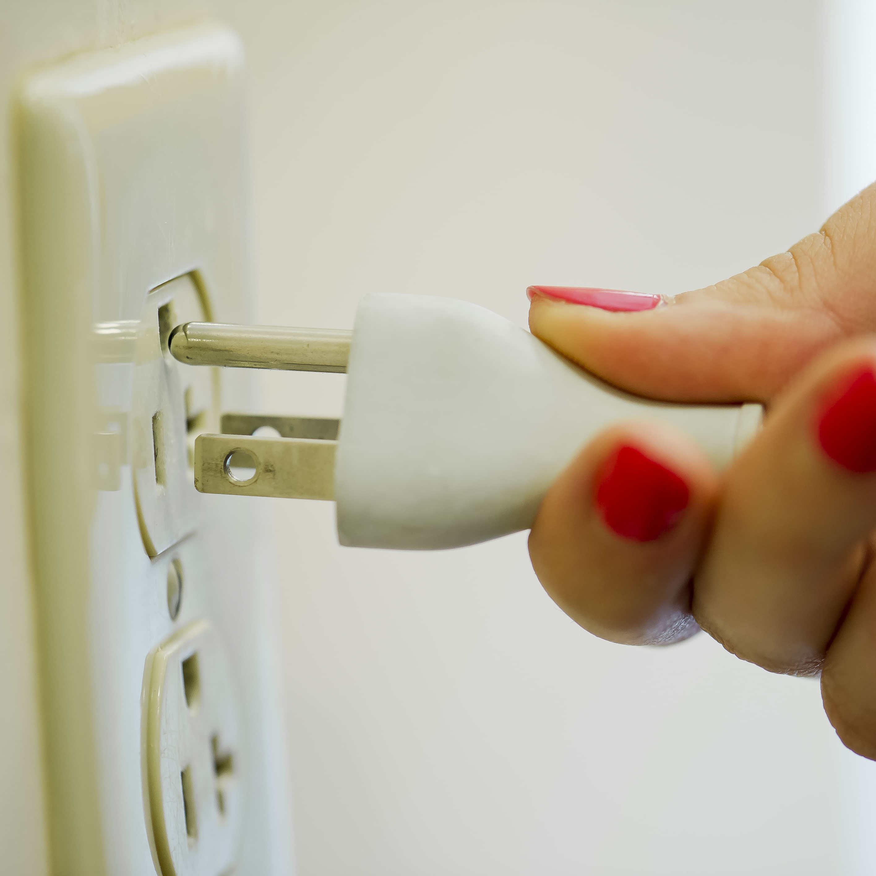
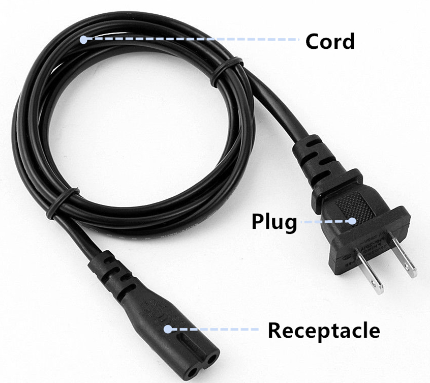
A power cord set usually has connectors molded to the cord at each end, thus both ends can detach from the power supply and device. Specifically, power cord assembly consists of three major parts. First is the cable plug, and it is also a male connector used for inserting into the AC outlet to provide power. Then is the receptacle on the other end. Receptacle part is also known as the female connector attached to equipment. Cord is the main section that contains the insulated wires with different lengths and thicknesses.
power cord structure

Common Types of Power Cord
According to different plug and receptacle styles, power cords have different standards. In North America, NEMA power cords and IEC 60320 power cords are the common types with the standards set by NEMA (National Electrical Manufacturers Association) or IEC (International Electrotechnical Commission). Let’s have a look at their differences.

NEMA Power Cord
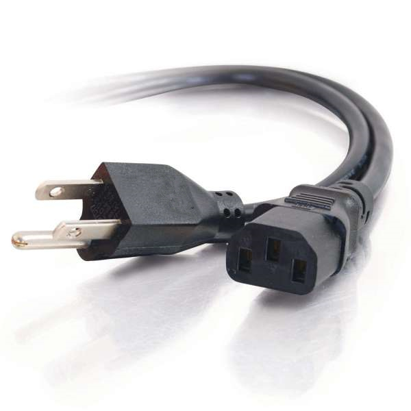
NEMA power cords have two series of NEMA 5 and NEMA 6. NEMA 5 series is the type widely found in the United States. It has three-wire circuits (hot, neutral, and ground) and is rated to carry a maximum of 125 volts although usually carries about 110 volts and are referred to as “110 circuits”. NEMA 6 series connectors are used for providing heavy duty power to a device. These are typically 208 volt or 240 volt circuits and often referred to as “220 circuits”.
NEMA Power Cord

IEC 60320 Power Cord
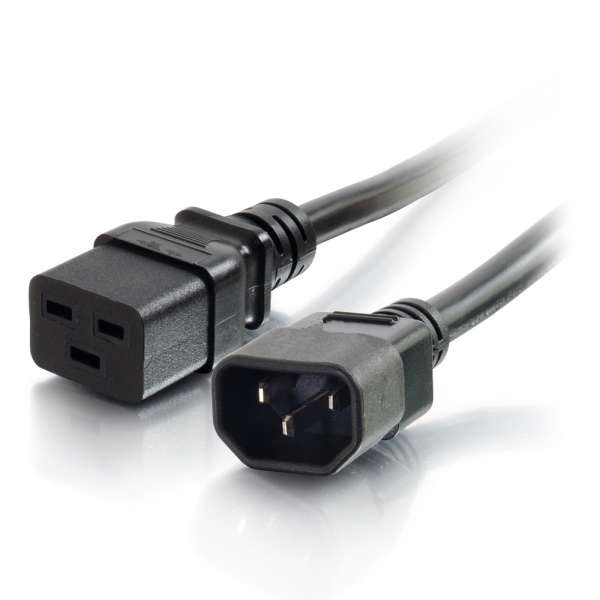
The ends of IEC 60320 power cord are on the opposite side of the cord from the power plug. To make it an international standard, the equipment manufacturers need to put one kind of receptacle on their equipment and then manufacture the various country-specific cords when needed. The IEC 60320 C13/C14 connector type is seen on most personal computers and monitors. C19/C20 connector type is used for devices like servers and UPS (Uninterruptible Power Supply) systems.
IEC 60320 power cord

How to Organize Power Cords?
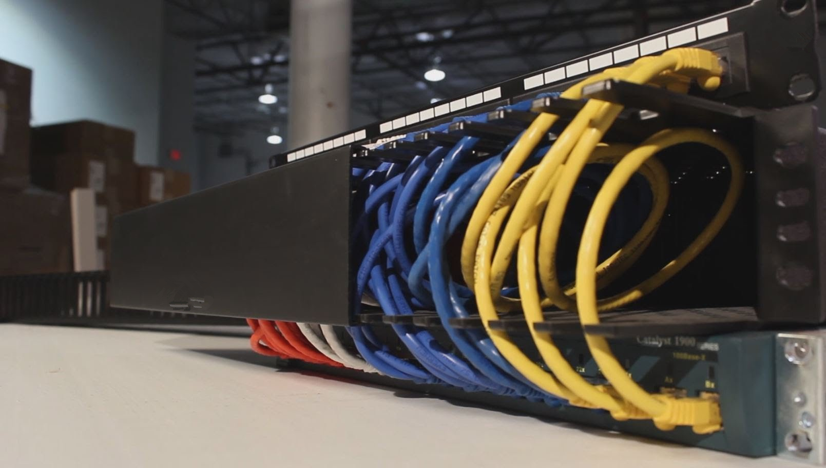
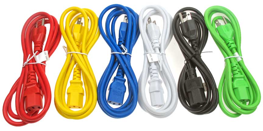
Just like other types of cables, too many power cords can also be easily mixed up during work. Fortunately, there is a simple way to organize the power cords. Instead of labeling all the power cords, you can buy the colored cords for identification. For example, red power cords can be used for important device, and green or blue cords can be used for constantly rearranged equipment. Color coding the system is definitely a more efficient way for cable management.
colorful power cord

Conclusion
The standardization of power cords provides great help for the convenient connectivity when powering different kinds of devices. There is usually a long list of power options for the switch or server. You might be confused when all the components are using the acronyms you don’t know. Therefore, understanding the standards can make the selection of power cords much easier.

2017年1月15日星期日

Basic Knowledge of Wireless Access Point

With the rapid development of Ethernet network, cables are widely adopted for wired network connectivity. However, this may also lead to the problem of cable mess when large quantities of cables are deployed. In order to solve this issue, wireless network is now accepted by most network users to reduce the employment of cables. Wireless access point is an important device for connecting the wired network with wireless network. This article will talk about the fundamental knowledge about wireless access point.

What Is Wireless Access Point?
Wireless access point (WAP) is also known as access point (AP). It is a hardware device used in a wireless local area network (WLAN) for data transmitting and receiving. An access point connects users to other users within the network and also serves as the point of interconnection between the WLAN and a fixed wire network. Basically, the working principle of wireless access point is to broadcast a wireless signal that computers can detect, then computers can link to the network without using any wires.
wireless access point

Categories of Wireless Access Point
Fat Access Point
According to different working modes, wireless access point can be divided into several categories. Fat access point is the standard type which is also named as autonomous access point. This device is independent to be separated from other network devices or fat access points. It can automatically manage the functions for wireless client devices, such as wireless authentication and encryption. It is enough to use the fat access point at home or small office.
fat AP

Thin Access Point
However, when wireless access point is required in large enterprise or college campus, fat access point is not an ideal solution. Thin access point, namely lightwave access point, may be a better choice with all the functions controlled in a central device, like a wireless switch or wireless LAN controller. Thus, all the settings can be configured automatically by central device in a remote location.
thin AP

Fit Access Point
Fit access point is the combination of both fat and thin access points. It provides the wireless encryption function and has a remote controller for management. Fit access point can also support the DHCP (dynamic host configuration protocol) relay to get IP address for the station.

Applications of Wireless Access Point
Indoor
Wireless access point used indoors are comparatively smaller for easier installation and maintenance. Signals broadcast from indoor access points are stable and high-qualified. Wireless radiation is also weaker which makes the indoor device ideal for dense deployment.

Outdoor
As for the outdoor application, access points are more solid to survive the harsh environment. Network signals are more stable with a bigger coverage. Point to point and point to multi-point network connections are widely used for outdoor application to link the networks among different locations.

Are Wireless Router & Wireless Access Point the Same?
The answer is no. A router can be an access point but an access point can’t be a router. A router is able to provide WiFi access and has an Ethernet switch built in, while an access point is to connect the wired Ethernet LAN to WiFi devices.
wireless router and wireless access point

Conclusion
Nowadays, wireless network is everywhere around us saving a lot of troubles for managing cable mess. A wireless router is often enough for family use since the coverage is limited. However, if you need to build up wireless network in large areas, wireless access point is always necessary.

2017年1月11日星期三

Data Center Architecture Designs Comparison: ToR Vs. EoR

The interconnection of switches and warranty of data communication are the basic aspects to consider when designing a data center architecture. Today’s data centers have been shifted into 1RU and 2RU appliances, thus setting the 1RU and 2RU switches into the same-sized racks can greatly save space and reduce cabling demands. Typically, Top of Rack (ToR) and End of Row (EoR) are now the common infrastructure designs for data centers. In this article, we will mainly discuss the differences between these two approaches.
tor-eor

Overview of ToR & EoR
What Is ToR?
ToR approach refers to the physical placement of network access switch in the top of a server rack. Servers are directly linked to the access switch in this method. Each server rack usually has one or two access switches. Then all the access switches are connected with the aggregation switch located in the rack. Only a small amount of cables are needed to run from server rack to aggregation rack.
top-of-rack

What Is EoR?
In the EoR architecture, each server in individual racks are directly linked to a aggregation switch eliminating the use of individual switches in each rack. It reduces the number of network devices and improves the port utilization of the network. However, a large amount of cables is needed for the horizontal cabling. Along with the EoR approach, there is also a variant model named as MoR (Middle of Row). The major differences are that the switches are placed in the middle of the row and cable length is reduced.
end-of-row

Comparison Between ToR & EoR
Benefits
As for ToR, the cost of cables are reduced since all server connections are terminated to its own rack and less cables are installed between the server and network racks. Cable management is also easier with less cables involved. Technicians can also add or remove cables in a simpler way.

In the EoR, device count is decreased because not every rack should equip the switches. Thus, less rack space is required in the architecture. With less devices in data center, there will be less requirements for the cooling system which also reduces the using of electricity power.

Limitations
In reverse, there are also some limitations for each architecture. For ToR, although the cables are reduced, the number of racks is still increased. The management of switches may be a little tricky. In addition, ToR approach takes up more rack space for the installation of switches.

As for EoR, its Layer 2 traffic efficiency is lower than the ToR. Because when two servers in the same rack and VLAN (virtual local area network) need to talk to each other, the traffic will go to the aggregation switch first before comes back. As less switches are used in EoR design, more cables are deployed between racks triggering higher possibility of cable mess. Skillful technicians are required when carrying out the cable management.

Physical Deployments of ToR & EoR
ToR Deployment
One is the redundant access switch deployment which usually demands two high-speed and individual ToR switches that connect to the core network. Servers are interconnected to access switches deployed within the server racks. Another is the server link aggregation with ToR deployment. Two high-speed ToR switches are part of the same virtual chassis. Servers can connect to both of the switches located at top of rack with link aggregation technology.

EoR Deployment
EoR access switch deployment is very common to extend all the connections from servers to the switching rack at the end of row. If the deployment is needed to support the existing wiring, you can also deploy a virtual chassis.

Conclusion
ToR and EoR are the common designs for data center architecture. Choosing the proper one for your network can promote the data center efficiency. From this article, you may have a general understanding about these two methods. Hope you can build up your data center into a desired architecture.

2017年1月10日星期二

Cable Manager Brings Cable Routing Back to Life

Along with the trend for high density connectivity in server rooms or data centers, cable management has become more difficult than ever before. Cable mess often occurs on the racks causing tremendous problems for later installation and cable maintenance. Network installers are searching for effective tools to make structured cabling. Cable manager appears to be an optimal management accessory. Today, many places adopt this component for cable routing in a simpler way. This article aims to introduce some cost-effective cable manager solutions for you.
cable manager

Benefits of Cable Manager
With the help of cable manager, cables are perfectly protected from strain to ensure the network reliability. Besides, cable manager also ensures the data integrity in a more organized way. Space is rationally used with a safer cable routing. It is pretty simple to install the cable manager and use it to arrange large amount of cables. The cost of cable manager is always affordable which is a necessary invest to avoid huge loss caused by cable mess in the future.

Cable Manager Solutions
Orientations
Cable manager can be used for either horizontal direction or vertical direction. The horizontal cable manager allows neat and proper routing of cables from devices in racks. It is important to make sure the rack height and cable density is supported by the cable manager. Typically, 1U and 2U horizontal cable managers are more popular in use. You also need to ensure that the horizontal cable manager is not obstructing devices in racks and cables are free to add or remove. Another solution is vertical manager. It can arrange the slack patch cables in vertical space allowing for 50 percent growth of cables and eliminating the use of horizontal cable managers.
cable manager orientations

Styles
Cable manager usually has various styles. First is the type with finger duct. The flexible finger ducts can maximize the care and protection of the equipment and cables. The holes are easy to pass through for convenient cabling. Second type has the D-rings and is available for horizontal, vertical or diagonal positions in cable management. Third is the cable manager with brush slots. This unique design can protect the cable from most contaminants and effectively increase the air flow at the same time. Last cable manager style is especially used for telephone line. It is often constructed by a base within two 110 cable management blocks.
cable manager styles

Structure
Structures of cable manager can be divided into single sided and dual sided types. Single sided manager provides a convenient cable run between equipment and racks, while dual sided manager supports patch panels by keeping different cables separate for better distinction.
cable manager structure

Material
Generally speaking, cable manager can be made of three kinds of materials as plastic, metal and semimetal. Plastic and metal are the most common materials. Plastic cable manager is definitely lighter in weight for easier installation. Metal cable manager is more solid to protect the cables from any damage.

Conclusion
In summary, cable manager is now widely used for cable routing in racks. Having a structured cabling is beneficial to future management of cables. It’s never too late to sort out the cables if you want your network to achieve a higher performance for data transmission. FS.COM provides all kinds of cable managers mentioned above. If you are interested, please visit www.fs.com for more information.

2017年1月4日星期三

Breakout or Distribution Cables — Which One to Choose?

Cables with multiple fibers are widely applied to high-density indoor or outdoor installations. Breakout and distribution fiber optic cables are the common used types. However, people may mix them together because they have a similar outer appearance. Actually, the inner structure of these cables are totally different. In this article, some differences between breakout and distribution cables will be discussed.

Cable Structures
Breakout Cable Structure
Breakout cable is also known as fan-out cable. As the following picture shows, breakout cable consists two or more simplex cables bundled around a central strength member. Each fiber has its own jacket and all of the fibers are packaged together inside the same outer jacket. Thus, breakout cable can also be broken out into individual simplex cables for separate use when running through walls of a building. Breakout cable is usually designed with tight buffer and the fiber counts are varied from 2 to 24 fibers.
breakout fiber cable structure

Distribution Cable Structure
Unlike the breakout cable, distribution cable is smaller in size and lighter in weight. Fiber counts of distribution cable can be more intensive than the breakout cable for up to 144 fibers. Many fibers may not be used immediately but can be left for future expansion. Although the distribution cable has a more compact design, the tight-buffered fibers inside the cable are only bundled in a single outer jacket for protection, as shown in the picture below. Yet this has made the distribution cable to be easily handled and stripped for field termination.
distribution fiber cable structure

Cable Types
Types of Breakout Cable
According to different fiber ratings, breakout cable can be divided into breakout riser cable and breakout plenum cable. Breakout riser cable is widely used for vertical riser and general horizontal applications. However, when the cable is needed for ducts, plenums and other spaces with environmental air returns, breakout plenum cable is the better choice.
breakout cable

Types of Distribution Cable
Likewise, distribution cable also has the riser and plenum cable types for riser and plenum spaces deployment. Apart from these types, distribution cable is sometimes equipped with armored jacket for a stronger protection. Armored distribution riser or plenum cable can be applied to harsh premise environments where heavy-duty protection is required.
distribution cable

Cable Applications
Breakout Cable Applications
Breakout cable may end up in communication closets, and users can manually change connections. It is also available to be used for direct connection to the device. Moreover, breakout cable is suitable for short riser or plenum areas and conduit runs, where a very simple cable run is planned to avoid the use of splice box or spliced fiber pigtails. Since breakout cable has a stronger design, it is ideal for industrial applications where ruggedness is needed.

Distribution Cable Applications
Distribution cable is typically used for fast installation and easy termination of outdoor and indoor applications. It supports high performance networks and its single-unit fiber design saves much space. Distribution cable usually ends up at patch panels or communication closets, where they are connected with devices for communications between separate offices or locations. Distribution cable is also used within buildings to provide high-density connectivity for applications of intra-building backbones, routing between telecommunications rooms and connectorized cables in riser and plenum environments.

Conclusion
In summary, it is a convenient solution to use breakout or distribution cables for multi-fiber applications. Certainly, when you have to make a choice between them, you also need to consider the price factor. Breakout cable is generally stronger and larger than the distribution cable, thus the cost will be more expensive. Be sure to have a second thought before making the decision.

Rated Cables Comparison: Plenum Vs. Riser

Whenever constructing cables into a building, we always need to consider the installation places. Different spaces may result in using the different cables. Plenum and riser areas are two common places for cable deployment. According to this, cables are rated into distinctive fire ratings as plenum cables and riser cables. This article is going to present a brief comparison between these two types of cables.

Introduction to Plenum & Riser
What Is Plenum?
In a building, a plenum is a separate space used for air circulation for heating, ventilation, and air-conditioning. The space is often between the structural ceiling and a drop-down ceiling. Sometimes, plenum also refers to the space under a raised floor. Since the plenum areas is a renewable source of oxygen and distribute environmental air, the cables installed in this area should have higher fire resistance. The typical application of this space is to house the communication cables for building’s computer and telephone network.
Plenum

What Is Riser?
Different from the plenum, a riser is a vertical area that passes from one floor to another floor inside a building. For instance, elevator shafts and conduits from one floor to another floor are all risers. Cables planted in risers should also be fire-proof to prevent the flame from traveling up the cable. However, the fire rating requirements for riser areas are less strict than those for plenum areas.
Riser

Differences Between Plenum & Riser Cables
In North America standard, CMR and CMP are used to describe riser and plenum cables. “C” and “M” are used to indicate that the cable is complied with the NEC (National Electrical Code). “R” refers to riser and “P” refers to plenum. Here will illustrate the main characteristics of plenum and riser cables in the following parts.

Plenum Cables
Plenum cables, or CMP cables are installed in the plenum areas of buildings. This type of cables has a fire retardant plastic jacket. Materials of the jacket is either the low-smoke polyvinyl chloride (PVC) or the fluorinated ethylene polymer (FEP). If the cable comes across a fire, only little toxic fumes will emit as it melts. Plenum rated cables have a higher fire rating for both commercial and residential use. When cables are needed in the air ducts, plenum cables are the primary choice.
plenum cable

Riser Cables
Riser cables, namely CMR cables, are widely used for regular networking from floor to floor in non-plenum areas. Since the demands for riser cables are lower, plenum cables are usually used as an alternative of riser cables. However, replacing the plenum cables with riser cables is not available. Riser cables can also be applied to both commercial and residential areas, but residential homes are more common.
riser cable

Acronyms for Plenum & Riser Cables
Here lists some regular acronyms for plenum and riser cables, you may use them for a quick reference.
  • CMP: Communications Plenum. It can be installed in any space.
  • CMR: Communications Riser
  • CATVP: Cable TV Plenum.
  • CATVR: Cable TV Riser
  • CL3P: Class 3 Plenum. Usually for in-wall installation in plenum, riser and general spaces.
  • CL2P: Class 2 Plenum. Usually for in-wall installation in plenum, riser and general spaces.
  • CL3R: Class 3 Riser. Usually for in-wall installation in riser and non-riser spaces.
  • CL2R: Class 2 Riser. Usually for in-wall installation in riser and non-riser spaces.
Conclusion
Choosing the right type of rated cables can effectively reduce loss and is healthier to people when the cables are burning. Plenum rated and riser rated cables are generally employed for building constructions. If your application is related to the areas mentioned in the article, using plenum and riser cables is very necessary.