2016年9月29日星期四

Overview of SMF & MMF 40G QSFP+ Transceiver

Owing to the server consolidation, virtualization, and performance improvements in data centers, there is a demanding need for upgrading 10G switch connections into 40G connections. However, the reduced reach of OM3/OM4 multimode optics from 10G to 40G and the need to improve the existing fiber optic cabling plant based on additional fiber count both increase the difficulties of the upgrade process. Luckily, the advent of SMF and MMF 40G QSFP+ transceiver has solved the problem.

Basic Introduction to SMF & MMF 40G QSFP+ Transceiver
40g-qsfp-plus
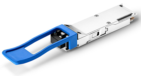
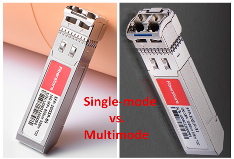
As we all know, a fiber optic transceiver may either operate on multimode fiber (MMF) or single-mode fiber (SMF). However, a SMF&MMF 40G QSFP+ transceiver can be used with both MMF and SMF without the need for any software/hardware changes to the transceiver module or any additional hardware in the network. Usually, this transceiver is based on IEEE defined 40GBASE-LR4 specifications and operates in the 1310 nm band. It uses a duplex LC connector and supports distances up to 150 m over OM3 or OM4 multimode fiber and up to 500 m over single-mode fiber (different vendor may have different specifications). This is usually accomplished by combining four 10G optical channels at different wavelengths (1270, 1290, 1310, and 1330 nm) inside the transceiver module to transmit and receive an aggregate 40G signal over a single pair of multimode or single-mode fibers. At present, there are two main SMF&MMF 40G QSFP+ transceiver in the market. One is the Arista QSFP-40G-UNIV universal QSFP+ transceiver, and the other is the Juniper JNP-QSFP-40G-LX4 40GBASE-LX4 QSFP+ transceiver. These two types QSFP+ for both MMF and SMF are widely installed and used for upgrading from 10G to 40G networks without modification or expansion.
Universal 40G QSFP+ Transceiver

Advantages of SMF&MMF 40G QSFP+ Transceiver
With the increase in data center bandwidth requirements, migration to 40G for switch to switch connections is in higher demand. SMF&MMF 40G QSFP+ transceiver is designed to allow for seamless migrations from existing 10 to 40GbE networking without requiring a redesign or expansion of the fiber network. Besides, this transceiver also provides a cost-effective solution to migrate from multimode to single-mode fiber, allows a single-mode fiber infrastructure for distances up to 500m. The advantages of SMF&MMF 40G QSFP+ are as following.

Cabling Migrating From 10G to 40G
Existing 40G transceivers for short reach, QSFP+ SR4 and the extended reach QSFP+ CSR4, utilize four independent 10G transmitters and receivers for an aggregate 40G link, which use an MPO-12 connector and require 8-fiber parallel multimode fiber (OM3 or OM4). However, a SMF&MMF QSFP+ uses duplex LC connector, which is consistent with the existing 10G connections, which are also commonly MMF cables with duplex LC connectors. Therefore, a SMF&MMF QSFP+ allows the same cables to be used for direct 10G connections to direct 40G connections, resulting in zero-cost cabling migration.
Fiber-requirements-for-a-single-link-using-SR4-or-universal-QSFP

Increase Number of 40G Links in the Network
As existing MMF 40G solutions need the use of 8 fibers for a 40G link, customers have to add additional fiber to increase the number of 40G links. By deploying the SMF&MMF 40G QSFP+ transceiver, customers increase the number of 40G links by 4 times without making any changes to their fiber infrastructure, which greatly expand network scale and performance.

Migrate From Multimode to Single-mode Fiber
As data rates increase from 40G to 100G and beyond to 400G, there is a strong desire for data centers to move to single-mode fiber for cost effectiveness. Due to the limitations of multimode transceivers to support existing distances with ever increasing data rates, migrating to 100G and 400G in the future will be simpler with single-mode fiber. However, the single-mode transceivers typically cost up to 4 times more compared to multimode transceivers. As SMF&MMF QSFP+ interoperates with 10km QSFP-LR4 optics, it s a cost effective solution for SM fiber infrastructure for distances up to 500 m.

Simplify the Data Centers With a Mix of MMF and SMF Deployments
The SMF&MMF 40G QSFP+ transceiver offers the unique advantage of operating on both multimode and single-mode fiber without any requirement for additional hardware or software. Customers can consolidate their optics and use SMF&MMF QSFP +in their network irrespective of the fiber type, which makes full use of the existing cabling systems, reduces the cost of deployment and of support, and simplify purchasing and deployments.

Conclusion
With the help of SMF and MMF QSFP+ transceivers, the upgrading from 10G to 40G networks can be perfectly achieved today. This solution saves the modification of cabling system which originally might be a huge cost. It also bridges the gap between single-mode and multimode optics. If you are interested in these transceiver products, please search our website for more information.

Why Use Media Converters in LAN & MAN?

media-converterNowadays, people are widely using media converters for LAN (Local Area Networks) and MAN (Metro Area Network). As for the LAN, media converter plays an important role in combining the fiber optic cabling and active equipment with the current copper structured cabling. And in the case of MAN, media converter is also significant in conversing electrical signals into optical signals which increases the service deployment and decreases the service cost for customers. This post is going to further explain the advantages of using media converters in LAN and MAN respectively.

Advantages of Using Media Converter in LAN
At first, media converters are simple devices just used to connect two dissimilar media types such as twisted pair with fiber optic cabling. Today, category of media converters increases a lot. And the function of media converter is not single and can meet more requirements. Media converters including fiber to RJ45 converters, SFP Ethernet converters, OEO converters, mode converters, fiber video converters, etc. can be found in the market.

Copper and Fiber Conversion
Now some LAN is still structured with twisted pair wiring. As a result, the transmission distance is greatly limited with only 100 meters. To extend the data transmission distance, fiber cable gains the popularity since it can support longer transmission distance and it’s more and more inexpensive. But in practice, copper is familiar and easier to be installed. Besides, many network devices still have copper ports. It would cost too much to replace all the expensive equipment with fiber optics. So media converter is applied to realize the copper & fiber conversion with the cheapest price. Media converters make it possible to migrate a local network to fiber while maintaining the existing infrastructure.
10-100base-t-to-100base-fx-xrj45-media-converter

Speeds Conversion
When connecting legacy 10BASE-T network segments to a newer 100BASE-FX Fast Ethernet infrastructure, media converter is the best solution. With one RJ45 port and one SFP socket, this 10/100Base-T to 100base-X SFP Ethernet fiber media converter can mediate between 10/100M UTP ports and 100M optical fiber ports. And it can reduce electromagnetic interference and extend the distance up to 100 km. Media converters can support network speeds from 10 Mbps to 10 Gbps.
speed-conversion
Figure 2.  Media Converter Connecting Different Speed

 
Bridging Two LANs over Fiber
Media converters are also used to expand the reach of the LAN to cover more locations. A converter can connect multiple LANs to form one large “campus area network” that spans over a limited geographic area. As premises networks are primarily copper-based, media converters can connect two distance switches with single-mode fiber and extend the reach of the LAN up to 130 km.

Saving Cost for FTTD
Existing data rate in the LAN backbone at 100Mbps or Gigabit speeds, fiber can accommodate high-bandwidth applications such as streaming media and voice over IP for more secure desktop connections. Media converters can make FTTD (fiber to the desktop) cost-effective in the LAN. With media converters, the cost of expensive fiber home which requires all-fiber switches, patch panels and network interface cards can be saved by converting in the telecommunications room and at the desktop.fttd
Figure 3.  Media Converters Make FTTD a Reality.

Advantages of Using Media Converter in MAN
Ethernet is the dominate LAN protocol with the highest market penetration. Past 10/100Mbps connections in LAN can’t meet the demands for high-speed data traffic. With the publication of the 10, 40 and 100 Gigabit Ethernet standard, the applications space for Ethernet expands from the LAN to MAN.

Maintaining Optical Circuits
Media converters are deployed in the MAN to provide the physical layer connection and to bridge the bandwidth gap that exists between LAN and MAN. In the LAN, the structured cabling is often twisted-pair copper cable or multi-mode fiber. While the cabling is often single-mode fiber in the MAN. So media converters are used at both ends of the first mile to provide the electrical-to-optical conversion from the POP (point of presence) switching router to single-mode fiber, and back to 10/100/1000BASE-T Ethernet at the customer premises. At the same time, if the customer needs to increase the internet speed, the bit rate can be increased through the POP switch and the converter will automatically adapt to the increased speed, avoiding a visit to the customer site or POP.

Increasing Flexibility
Media converters can realize the connections between copper switch ports and optical access to get more flexible and further. Media converters can support multiple types of media from copper to multimode and single-mode fiber. Single-mode converters cover distances up to 80 km with 1310nm optics and even 130 km with 1550 nm optics.

Media converters can also enhance the consistency of service. On one side, if there is any problem, the network administrator can troubleshoot one circuit and keep other customers’ connections running. On the contrary, if a fixed port switch goes down, all connections will be down simultaneously when repairing a faulty port. On the other side, customers can used the media converter as an optical demarcation point, which brings cost savings and simplicity.

Conclusion
There are many benefits of using media converter in LAN and MAN, such as copper and fiber conversion, speed conversion, cost reduction, simple network troubleshooting and so on. Media converter is not only the optical demarcation between LAN and MAN, but also the bridge between LAN and optical backbone of service provider. With such a cost-effective solution, what’s the reason not to use?

2016年9月27日星期二

Cat 5e or Cat 6 - Which Do You Choose?

As one type of copper cabling, twisted pair wiring is widely adopted for Ethernet networks which wraps the two conductors of a single circuit together. Nowadays, many kinds of twisted pair cables are available in the market. To specify the cable wiring standards, the Electronic Industries Alliance (EIA) and Telecommunications Industry Association (TIA) have defined twisted pair cables into a series of categories, such as Cat 5, Cat 5e, Cat 6, Cat 6a, Cat 7, etc. This article will put emphasis on the two common categories of Cat 5e and Cat 6 to see their differences and which one to choose for your application.
cat5e-cat6

Wiring Standards of Cat 5e & Cat 6
Two standards of T568A and T568B can be used to wire Cat 5e and Cat 6 Ethernet cables. The only difference between T568A and T568B is that the green/green strip and orange/orange strip wire positions are swapped. In general, T568B is more popular for office and commercial networks. But no matter which wiring standard you choose, the most important thing is to continue with the selected standard for consistency. The following picture shows the concrete structure of T568A and T568B wiring.
t568a-t568b

Differences Between Cat 5e & Cat 6
Speed
Data speed is important for cable selections. You have to choose the cable that is equivalent to what is running on it. As for Cat 5e cable, it can support 1 Gigabit Ethernet. While Cat 6 can support higher data rate of 10 Gigabit Ethernet. This is because Cat 6 cable performs up to 250 MHz, which is more than twice that of Cat 5e cable with 100 MHz.

Maximum Length
The common ground for Cat 5e and Cat 6 cables is that they are all designed for short distance data transmission because they are made of copper wires. If the cable is used for lower data rate transfer, both Cat 5e and Cat 6 are able to reach the maximum length of 100 meters. However, when the data rate achieves the maximum speed, Cat 5e cable can only reach 50 meters and Cat 6 with 37 meters.

Cost
Compared with Cat 5e cables, the cost of Cat 6 cables is typically 10 to 20% more expensive because of higher transmission speed. But the price of these cables are comparatively cheap, which only takes up a small portion of the total budget. For the consideration of your application, Cat 6 might be a better choice if higher data rate is required. The additional cost can save you more money in the long run.

Application
Traditionally, Cat 5e cable is run for the business telephones. But using Cat 6 cable with a phone might be a waste. Cat 6 is suited for broadband video and digital video applications because of the lower signal losses and better transmission performance at higher frequencies compared with Cat 5e.

Can We Use Cat 5e With Cat 6?
The answer is yes. Regardless of a possibly different coating on the pins, Cat 5e and Cat 6 are both employing the RJ45 plug standard which makes them compatible to each other. But you can only receive a limited speed of the lowest link in the chain. Therefore, if you want to receive the best performance of cables, you should better use the matching components for your application.

Conclusion
Cat 5e and Cat 6 are two different categories of twisted pair cabling. The major difference between them is the data speed. Cat 6 has a higher speed than Cat 5e which accordingly varies their maximum length, cost and application. All these factors are important for you to make a choice between Cat 5e and Cat 6. Moreover, if higher speed over long distance is demanded, fiber optic cables might be a better solution.

2016年9月24日星期六

Differences Between Single-mode & Multimode Fiber Optic Transceivers

As for data transmission in optical networks, fiber optic transceiver is an indispensable part used for sending and receiving electrical and optical signals between facilities like computers, input/output devices, peripheral devices or switches. According to different transceiver models, optical modules can be divided into single-mode fiber optic transceivers and multimode fiber optic transceivers. Each type has its own different characteristics. You need to know their differences so as to choose the most suitable type. To understand them better, this post will present their brief introduction and major differences.

What Is Single-mode & Multimode Fiber Optic Transceivers?
A single-mode fiber transceiver is a type of optical transceiver module, which is a self-contained component that can receive and transmit data using single-mode optical fiber cables. It permits the transmission of signals at the very extreme high bandwidths thus facilitating the transmission of signals at very long distances. A multimode fiber optic transceiver works with multimode fiber. It permits the use of inexpensive LED light sources and alignment of the connectors with a coupling that is less critical than that of the single-mode fiber. The transmission distance of multimode fiber optic transceiver is less than that of the single-mode transceiver due to dispersion.
single-mode-and-multimode-transceiver

What Are Their Differences?
The major differences between single-mode and multimode fiber optic transceivers are listed below.

Transmitting Rates and Range—Both the single-mode and multimode fiber optic transceiver can handle the 10G speeds. However, distance requirements are quite critical. The multimode optical transceivers generally have a reach of approximately 550 meters, while the single-mode transceivers can get you through 10 km, 40 km, 80 km and even farther.

Price—The optics used in the single-mode fiber are twice those used in the multimode fiber. But when installed as part of a project, the extra cost of single-mode fiber is negligible compared to multimode fiber. The fragility and increased cost to produce single-mode fiber makes it more expensive to use.

Compatibility—When it comes to issues dealing with compatibility, the two types of transceivers are not compatible. You cannot mix the multimode and the single-mode fiber between any two endpoints.

Power Dissipation—Multimode transceivers consume less power than single-mode transceivers, which is an important consideration especially when assessing the cost of powering and cooling a data center.

What Should Be Noticed When Using Them?
When using the fiber optic transceivers, the tips below should be followed.
  • Ensure that in the single-mode transceivers, both ends of the fiber patch cord are of the same wavelength. The color for the used modules must be all consistent.
  • In order to ensure and facilitate the data accuracy, short wave modules are used with the multimode transceivers while long wave modules are used with the single-mode transceivers.
  • Do not wind or overbend the fiber optic cables when using them. This is because doing so will attenuate the light in transit.
Conclusion
From this article, we can know that single-mode and multimode fiber optic transceivers are used for different applications. Single-mode optical transceiver is typically used for high speed data transmission over long distances. But multimode optical transceivers are made for short fiber optic links. Our website provides fiber optic transceivers with different data rates such as 10G transceivers40G transceivers100G transceivers, etc. supporting both single-mode and multimode transmission. All of them are tested on the corresponding equipment to ensure their performance and stability.

2016年9月23日星期五

Have You Used Optical TAP Cassette Before?

In today’s intelligent data center, real-time monitoring has become an important part to secure the network for better performance. Is there any device that can achieve both data transmission and monitoring at the same time? Certainly, optical TAP (traffic access point) cassette is the ideal solution. This hardware tool enables you to monitor every bit, byte and packet of your data information. If you are not familiar with this type of device, the article is going to explain it to you.

Basics of Optical TAP Cassette
Optical TAP is an access point install in networks that provides real-time monitoring of ports. Typically, the data is used to monitor for security threats, performance issues, and optimization of the network. Optical TAP cassette is a passive device that integrates TAP functionality into cable patching system, which requires no power of its own and does not actively interact with other components of the network. Instead of two switches or routers connecting directly to each other, the optical TAP cassette sits between the two endpoint devices connected directly to each of them. Then traffic is copied and once the traffic is tapped, the copy can be used for any sort of monitoring, security, or analytical use. Thus, TAP cassettes are a key component of any visibility system.
TAP cassette

Operation Principle of Optical TAP Cassette
Optical fiber is designed to send light from a transceiver through a thin glass cable to a receiver on the other end. Instead of connecting directly to each other, each of the two endpoint nodes (switches, routers, database, etc) are connected to network ports on the TAP cassette. A TAP cassette usually integrates both network ports and monitoring ports in a module and it includes an optical splitter, which “splits” off a percentage of the input power and sends it to a monitoring device. As shown in the figure below, we can connect the TAP cassette to the Switch X and Switch Y via network ports and connect TAP cassette to monitoring device via monitoring ports.
TAP cassette


By using the splitter, we can see that a part of TX data of Switch X transmits to RX of Switch Y and another part of TX data of Switch X transmits to monitor. Similarly, a part of TX data of Switch Y transmits to RX of Switch X and another part of TX data of Switch Y transmits to monitor. The monitored traffic is thus separated into two transmit (TX-only) signals, one copy from endpoint A (Switch X), and one copy from endpoint B (Switch Y). The proportional share of light for each path (transmit to network and monitor) is known as the split ratio. The split ratio is written as a combination of two percentages. The first number is designated as the network percentage. The second number is the monitor percentage. They always add up to 100 percent. For example, a common split ratio for traditional 1Gb short-range links is 70/30, where 70% of the light continues to the network and 30% is allocated to the monitor port.

Connecting Your Optical TAP Cassette
Before you connect the fiber optic cable into a TAP cassette, make sure that the TAP cassette is compatible with the cables. At present, TAP cassettes are mainly available in LC and MTP two port types. Take the MTP TAP cassette for example, and following steps will show you how to connect an optical TAP cassette to your network:
TAP LGX cassette

To connect TAP cassette to the network (in-line links)
  • Step 1, connect MTP network port to switch A using a MTP cable.
  • Step 2, connect another MTP network port to switch B using a MTP cable.
To connect TAP cassette to the monitoring device
  • Step 1, connect TAP monitor port to monitoring device using a MTP cable for switch A monitoring.
  • Step 2, connect another TAP monitor port to monitoring device using a MTP cable for switch B monitoring.
Conclusion
Optical TAP cassette makes it possible to monitor and transmit optical data simultaneously. Technicians are able to gather valuable data analytics and detect network traffic issues in a timely manner. Optical TAP cassette has been widely used in data centers and telecom carrier networks. If you are interested, please visit FS.COM for more information.

2016年9月22日星期四

Applying VFL for Fiber Cables Troubleshooting

Whenever you need to install or troubleshoot fiber cables, visual fault locator (VFL) is an easy and essential tool for quickly positioning the problem areas. As a fiber optic tester, VFL is used to trace optic fibers, check fiber continuity and find fiber breaks, damaged connectors, defective splices, tight bends in optical cables. Two basic types of VFL are pen shape VFL and hand held VFL. Pen shape VFL is very small with a pocket size to be carried anywhere. Hand held VFL has a range of connector bulkheads styles from universals to specific connector types. This article will lead you to know more information about VFL.
visual-fault-locator

Importance of VFL
VFL can pinpoint the exact fiber damage location, therefore technicians are able to diagnose and solve the problem in a timely manner which efficiently avoids further fiber damage. VFL is also used for conducting continuity tests and performing fiber identification. With the help of VFL, specialists can easily isolate high losses and faults in optical fiber cables. As we all know, a good cabling system is the pledge of a good data center. In order to maintain the perfect functioning of fiber optic cables, VFL is an indispensable tool to be applied for the routine trouble shooting.

How VFL Works?
The invisible light signals are typically transmitted at 1300 nm to 1650 nm wavelengths over fiber optic cables. Different from the way that OTDR (optical time-domain reflectometer) locates the faults by measuring the time of the incidence and the amplitude of the reflected pulses sent to the fiber optic cable, VFL uses powerful visible light at the wavelengths between 360 nm to 670 nm to visually and quickly locate the faults in the cables. When the visible light leaks out at a certain point of optical cable, it shows that the VFL has reached a fault. It is also easy to see light leaking through the plastic cable jackets under the right illumination of VFL. Generally, a VFL can work at the distance between 2 km to 5 km.

How to Use VFL?
Using VFL is not a difficult task. Just follow the steps to know the operation procedure:
  • Step one, remove the plastic connector covers from both ends of the fiber cable.
  • Step two, connect the VFL to one end of the fiber cable.
  • Step three, press the tester button and observe whether light emanates from the other end of the fiber. This gives a simple indication of the continuity of the fiber link.
  • Step four, repeat the above steps with other fiber cables to see if visual light is leaking out from a faulty splice. This may illustrate an easy way of carrying out visual fault locating on bad splices or joints.
  • Step five, disconnect all equipment, put the plastic covers back to the connector ends and return everything to the state it was.
Notes:
  • Point one, do not look directly into the VFL’s output.
  • Point two, cover the VFL’s output with the dust cap when it is not in use.
  • Point three, VFL is not recommended to be used on dark colored or armored cables.
Conclusion
VFL is an equipment for fiber testing, troubleshooting and measurement. It is ideal for locating a large number of defects that are hidden in an OTDR “blind-spot” or “dead-zone”. Fiber breaks, faulty connectors, sharp bends, bad splices and other similar faults can be visually located by VFL’s visual light injected into a fiber. VFL can boost productivity in the field by providing fast detection, precise fault location and ORL (optical return loss) measurements. If you don’t have it, better get one for your project.

2016年9月14日星期三

No More Worries for Cable Bending

Under general conditions, fiber patch cables are not allowed to be bent beyond bend radius in case of light leaking. However, when installing cables at high-density environments, cable bending is hard to avoid. In order to solve the problem, bend insensitive fiber patch cable is designed to cause much lower optical power loss under bend conditions. In this way, cable bending won’t be an obstacle for your cable installation. This post will take you to explore the world of bend insensitive fiber patch cables.
bend insensitive fiber patch cables

Introduction to Bend Radius
Bend radius is the minimum radius one can bend a pipe, tube, sheet, cable or hose without kinking it, damaging it, or shortening its life. The smaller the bend radius, the greater is the material flexibility. When you install the cables, keep in mind do not exceed the cable bend radius. Usually, if no specific recommendations are available from the cable manufacturer, the cable bend radius should be smaller than 20 times the cable outside diameter when pulling the cable and 10 times the outside diameter when lashed in place. For example, while pulling a 2mm diameter cable allows for a 40mm sweep. When lashed in place make sure it’s a 20mm sweep. For most of today’s fiber patch cables, the bend radius is 30 mm.
Bend Radius

Multimode Bend Insensitive Fiber Patch Cable
Multimode Bend Insensitive Fiber Patch CableOur multimode bend insensitive fiber patch cables have a minimum bend radius of 7.5mm, which compares very favorably to the 30mm bend radius traditionally specified. To achieve this, an optical “trench” is added to the cladding area outside of the fiber core.  This trench retains more of the light that would have escaped the core of a traditional multimode fiber. Requirements for a tighter bend radius have been developed based primarily on factors in the fiber to the home (FTTH) market. However, the benefits for premise markets have rapidly become apparent, particularly in data centers where more and more fibers are being installed in smaller areas. The expectation is that this new feature can enable deployment of multimode fibers in higher densities.
Multimode Bend Insensitive Cable

Single-mode Bend Insensitive Fiber Patch Cable
Single-mode bend insensitive fiber patch cables have been commercially available for several years. ITU recommendation G.657 specifies two classes of single-mode bend insensitive fiber patch cables: G.657 A and G.657 B. Each category (A and B) is then divided into two sub-categories: G.
657.A1, G.657.A2 and G.657.B1, G.657.B2. The minimum bend radius of G.657.A1 fibers is 10 mm, of the G.657.A2 and G.657.B1 fibers is 7.5 mm and of the G.657.B2 fibers is 5 mm. Among, ITU-T G.657.A1 and ITU-T G.657.A2 fibers are fully compliant with ITU-T G.652.D fibers. Compared with minimum bend radius of the standard single-mode G652 fibers, which is usually 30 mm, G.657 single-mode bend insensitive fiber patch cables are much more flexible thus can be confidently installed with a variety of installation methods and in the increasingly high-density application spaces of today’s data center.
Single-mode Bend Insensitive Cable

Conclusion
If you want to be bent-free for cable installation, bend insensitive fiber optic cable is a perfect solution. Its solid trench helps reduce the cable bending optical loss. And this type of cable is as qualified and functional as the standard patch cables. Both multimode and single-mode fibers can be made bend-insensitive. A wide range of bend insensitive patch cord selections is waiting for you to choose.

Preparing MTP/MPO System for Different Applications

There is no doubt that 40G and 100G networks become the trend in today’s cyberspace. Many applications are pursuing the high bandwidth throughput, therefore using high-density patching is inevitable. But is there any good solution for high-density structured cabling? Definitely, MTP/MPO system solves your trouble with a wide range of MTP/MPO assemblies. It is a technique enabling multi-fiber connections to be used for data transmission. The high fiber count creates the endless possibilities of high-density patching. The easy installation of MTP/MPO assemblies also saves lots of operating time. This article will introduce some regular MTP/MPO products and their common applications.

Common MTP/MPO Products
To accommodate the needs for high speed networks, MTP/MPO system has many optics to fit for different applications. There are usually MTP/MPO cables, MTP/MPO cassettes, MTP/MPO optical adapter and MTP/MPO adapter panels.

MTP/MPO cables are terminated with MTP/MPO connectors at one end or both ends. The fiber types are often OM3 or OM4 multimode optical fibers. MTP/MPO cables has three basic branches of trunk cables, harness/breakout cables and pigtail cables. MTP/MPO trunks can be made with 8, 12, 24, 36, 48, 72 or even 144 fibers for single-mode and multimode applications. MTP/MPO harness cables are usually terminated with a MTP/MPO connector at one end and different connectors, such as LC, SC, ST connectors, etc. at the other end. Pigtails only have one end terminated with a MTP/MPO connector, and the other end is used for fiber optic splicing with no termination.
mtp-mpo-cables

As for the MTP/MPO cassettes, they are equipped with standard MTP/MPO connectors to be deployed in an ODF (optical distribution frame) for high-density MDA (main distribution area) and EDA (equipment distribution area) in data centers.
mtp-mpo-cassette

Other components like the black-colored MTP/MPO optical adapter and adapter panels build the connection between MTP/MPO cable to cable or cable to equipment.
mtp-mpo-optcial-adapter-and-adapter-panels

Applications
Data Center SAN (Storage Area Network)
MTP/MPO plug and play modules have been widely used in data centers, such as backbone products supporting hundreds of optical ports. Therefore, single cabinets must hold quantities of optical interconnections and patch cords. Since SAN needs high-density and modular cabling for easy reconfiguration, MTP/MPO plug and play modules are perfect to meet the requirements of these infrastructures.
data-centre-san

Data Center Co-Location
Co-location data centers require flexibility of network expansions for new customers or new services. The pre-terminated UHD (ultra high density) MTP/MPO system is ideal for fast and rapid deployment or expansions in these networks.
data-centre-co-location

Enterprise/Campus
UHD system modules can be installed in enterprise or campus networks using “plug and play” MTP/MPO or “just play” pre-terminated modules. Installation is fast and easy, which requires no professional fiber optics knowledge. Traditional splicing installation techniques can also be applied. There is a wide selection of cable types including tight buffer, loose tube, micro cable, etc. for employment.
enterprise-campus

Telecom Central Office
UHD system is a small footprint and is perfect for reduced space in high-density rack environments. Modules can be pre-terminated or feature MTP/MPO ports for improved reconfiguration. In addition, they can be fitted with splice management for traditional installation techniques.
telecom-central-office

Summary
In a word, MTP/MPO system is a perfect solution suited for high-density applications. The MTP/MPO products are designed to be space-saving and easy to manage. Initial investment for MTP/MPO assemblies might be expensive, but it is a wise and cost-effective decision to deploy the system for your application in the long run.

Are You Familiar With Optical Switch?

There are lots of fiber optical devices used for communication networks. And optical switch is the one transmitting light signals between different channels. If a light signal is propagated from one phone or computer to another, it may be required to move between different fiber paths. Under this condition, optical switch plays an important part as it can transfer the signal with a minimum loss of voice or data quality. With the growth of technologies, many new methods have been combined with optical switch to achieve higher speed performance. Today, let’s step into the world of optical switch and explore its secrets.
Types of Optical Switches
Basically, there are two types of optical switches - OEO (optical-electrical-optical) switch and OOO (optical-optical-optical) switch. Network management functions of operating a network are available today using an optical switch with an electronic-based switching matrix. OEO switch receives the optical signal and converts it into electrical signal. Then it switches the signal into a different port and converts it back to optical signal for the network. By using an electronic fabric, OEO switch accomplishes bandwidth grooming and overcomes the network impairments.
oeo-optical-switch
OOO switch or all-optical switch enables the managing and switching of optical signals without converting them into electronic signals. This is especially attractive to those carriers operating large offices where up to 80 percent of the traffic is expected to pass through the office on its way to locations around the globe. It receives the optical signal and switches it to a different port in the optical domain, then returns it back to the network as an optical signal.
ooo-optical-switch
Technologies Applied In Optical Switch
MEMS Switching
MEMS (micro electrical mechanical system) technology uses many moving mirrors to switch the signals by deflecting light waves from one port to another. There are two MEMS structures. One is called 2D MEMS mirror, and another is 3D MEMS mirror. 3D MEMS based optical switch is more widely used in the industry. Following figure shows the operation process of the MEMS switching.
mems-optical-switch
Liquid Crystal Switching
Liquid crystal technology employs the polarization effects of light in liquid crystals for light switching. At first, the light is filtered through polarization beam splitter to be separated into two or more paths. Then the light is put through a liquid crystal where its polarization property may be changed. At last, the light comes into the polarization beam combiner to be steered into the output port. And the output port is decided by the new polarization property of light.
liquid-crystal-optical-switch
Bubble Based Switching
Bubble based switch can use air bubbles and micro trenches aligned vertically and horizontally to switch the light. When there is no need for switching, the light can pass through the trenches uninterrupted. This technology has the benefits of low cost and fast switching time.
bubble-based-optical-switch
Thermo-Optic Switching
Thermo-optic switch will send light down a wave guard. The light is then split into different wave guards. If a switching command is issued, one of the wave guard arms is heated and the light within the wave guard will change its optical path length. Then the light is recombined and the path lengths of the lights are measured. If the lengths are different then the beam will be switched into one output port. If they are the same, the beam will be switched into another port.
thermo-optic-switch
Applications
Optical switches can be applied to various applications. In high speed networks, switches for this function are usually used within optical cross-connects to handle large amount of traffic. Another application is for the protection switching. If a fiber fails, the switch allows the signal to be rerouted to another fiber before the problem occurs. Also, the OADM (optical add-drop multiplexer) will use some optical switches to convert signals from a DWDM stream allowing carriers to selectively remove some wavelengths from a signal.
Conclusion
Optical switch is an important device that transfers light signals into different channels. Based on the original OOO type and OEO type optical switches, many new technologies have been brought in, which ensures the high performance of optical switches. With growing demands for higher data bandwidth, the future of optical switch is bright.