2016年8月30日星期二

Different Kinds of Cable Tie Solutions – Which Do You Prefer?

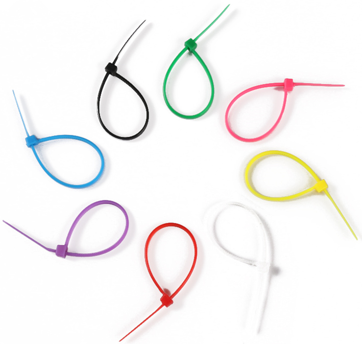
When you first saw a cable tie, you might feel nothing special about it. It’s just a tie for holding cables together, what more could it be? But the fact is that if you want to completely get rid of messy cables, cable ties are of great importance. They are generally inexpensive, and can be ordered in various colors and sizes. There are many types of cable ties on the market. Different types are made for various applications. Using the right cable tie can speed up your working efficiency. This article will introduce some common cable tie solutions. Maybe one of them is perfect for your project.
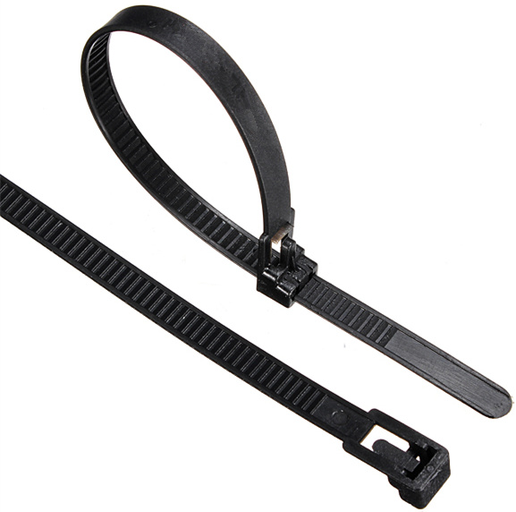
Self-locking Cable Tie
Self-locking cable tie has the classical oval lock structure for easy installation. It is the most common cable tie consisting of a flexible nylon tape with an integrated gear rack, and on one end a ratchet within a small open case. With a good locking design, cable tie can provide firm locking for the cables. This kind of cable tie is shorter and thinner for small spaces and light wire management. Its curved tip is easy to pick up from flat surfaces and allows faster initial threading to speed installation.
Self-locking-cable-tie
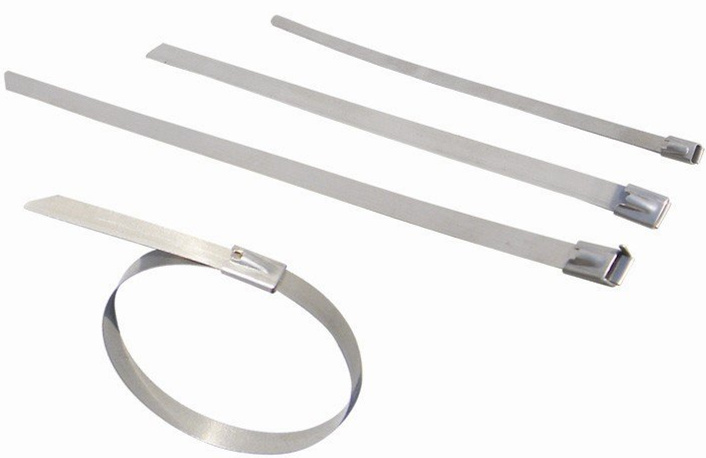
Stainless Steel Cable Tie
Stainless steel cable tie is used when there is liquid involved and when extreme temperatures are involved. This cable tie can withstand temperature ranging from -100 to +1000 degrees Fahrenheit. The stainless steel cable tie has a tensile strength of 100 lbs. And it has the capability to endure most chemicals that will cause corrosion. It can be used for the most extreme environment or where additional strength, security and fire resistance are required.
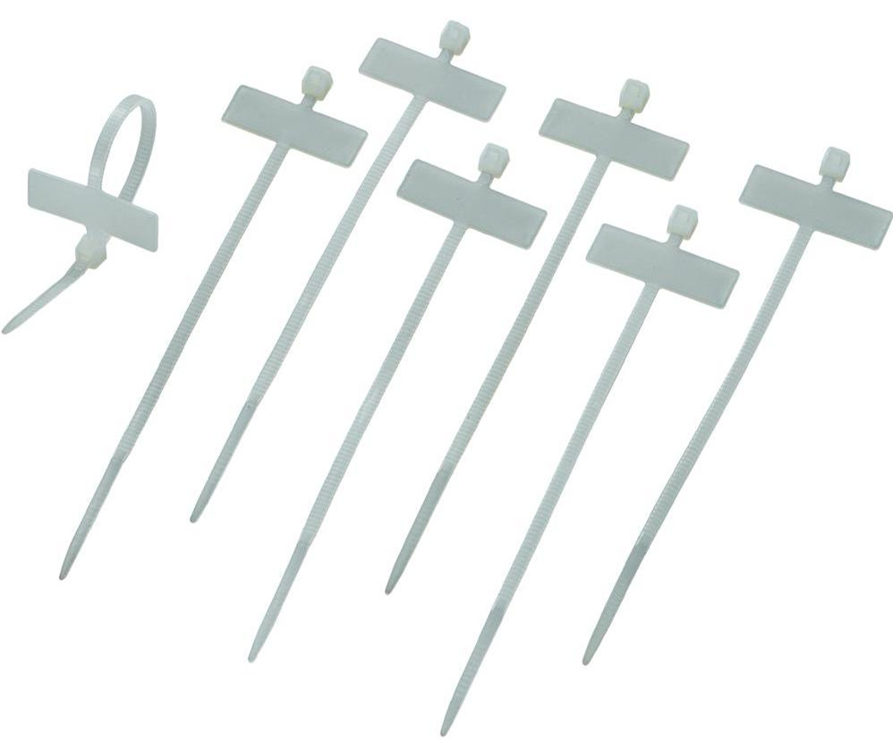
Stainless-steel-cable-tie
ID Marker Cable Tie
ID marker cable tie or identification cable tie features a large marker area for the imprinting or handwriting of cable assembly numbers and other vital information, making cable and wire identification in an extensive range of applications a fast and easy task. Whenever cable colors are not enough for cable identification, ID marker cable tie plays a part.
ID-marker-cable-tie
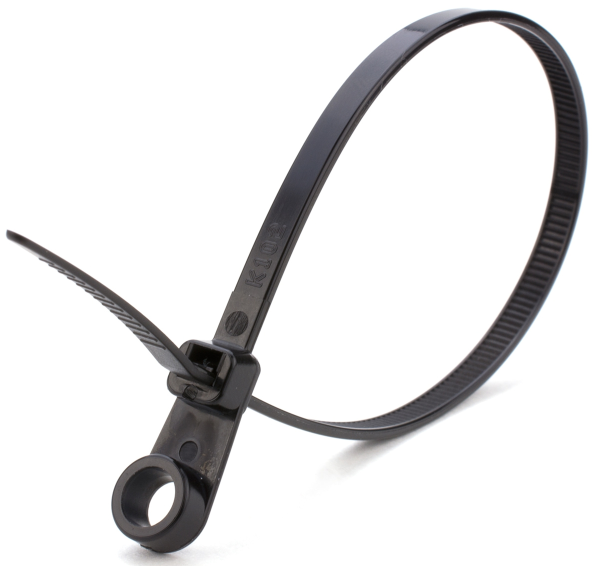
Mount Head Cable Tie
Mount head cable tie combines the zip tie and mounting eyelet together. It allows you to bundle cables and then mount them to a surface using screws, nails, clamps or clips. Surfaces including walls, ceilings, server racks, trailers, vehicle chassis, and other areas are able to handle the cables easily with mount head cable tie.
Mount-head-cable-tie
Releasable/Reusable Cable Tie
Releasable cable tie is actually reusable nylon self-locking cable tie. The common nylon cable tie can only be used once. If you need to re-bundle or rearrange the cables, then releasable cable tie is your best choice. By pressing the latch on the tough of cable tie, it can be easily released from the cables.
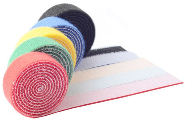
Reusable-cable-tie
Velcro Cable Tie
Velcro cable tie or hook and loop cable tie is made of a self-attaching hook and loop material. It is reusable and adjustable to support frequent moves, adds, and changes of cables. Usually sold in rolls, velcro cable tie can be easily cut down to any length you want. No matter for factory devices or household appliance, velcro cable tie is very convenient to be used for cable management. It also has many other types with different shapes such as the T type velcro cable tie, the voltage type velcro cable tie and the buckle velcro cable tie.
Velcro-cable-tie
Conclusion
Cable management is especially essential for device installations where large amount of cables are needed. As a cost-effective tool, cable tie can be simply mounted to arrange the cable mess which enables higher performance of devices. The above options are some common types in the market. You should choose the right cable tie according to your actual application.

2016年8月24日星期三

Application of 40GBASE-SR BiDi QSFP Transceiver

In short distance data transmission, 40GBASE-SR4 and 40GBASE-CSR4 fiber optic transceivers are usually used for the 40G network. Unlike the traditional 10G network connections, the 40G connections require 12-fiber MTP/MPO connectors and 12 fibers to accomplish the transmission. However, cable routing is definitely a big challenge for the migration from 10G to 40G network over short distance. If the transmission of 40G over duplex multimode fiber optic cable is feasible, we don’t have to change the cabling infrastructure which greatly saves our time and money.
Realizing 40G Over Duplex MMF By 40GBASE-SR BiDi QSFP
Is it possible to transmission 40G over duplex multimode fiber optic cables? With 40GBASE-SR BiDi QSFP transceivers, the answer is yes. The following will introduce the details of this optics. Compare with the traditional 40G QSFP+ transceivers like 40GBASE-SR4 and 40GBASE-CSR4, 40GBASE-SR BiDi QSFP optics use a much more straightforward transmission mode.
The traditional 40G QSFP+ transceivers like 40GBASE-SR4 and 40GBASE-CSR4 use 4*10G transmission mode occupying 4 fibers for sending and 4 fibers for receiving as shown in the following picture. Usually a 12-fiber MPO connector is used with 4 fibers unused.
mpo-interface
For 40GBASE-SR BiDi QSFP optics only a duplex LC patch cord can finish 40G transmission over MMF and can perfectly achieve the migration from 10G to 40G. 40GBASE-SR BiDi QSFP take advantages of fiber optic multiplexing.
Operations of 40GBASE-SR BiDi QSFP
There are mainly three steps for 4*10G signals transmitting via 40GBASE-SR BiDi QSFP module. The first step is electrical. The four 10G signals are electrically combined together into 20G and 20G. The second step is an optical combining using two different wavelengths going on the same fiber strand. In the third step, the two 20G signals are sent to the other 40GBASE-SR BiDi QSFP module on the target device via the single optical fiber. The 40G signals are receiveds from the other 40GBASE-SR BiDi QSFP module on the other end of the optical fiber. The process for receiving is reverse. This is how a pair of BiDi QSFP transmit 40G signals over a duplex fiber optic patch cable. The following picture shows the basic working principle of this 40G BiDi QSFP module.
40g-bidi-qsfp-work
The most commonly used two wavelengths for 40G BiDi QSFP module are 850 nm and 900 nm. The two wavelengths support reliable transmission over multimode fiber optic cables up to 150 meters over OM4 and 100 meters over OM3, which can perfectly fit the 40G short distance transmission in data center. To help you better understand this module. The following picture shows the internal structure of the 40G BiDi QSFP module and how a pair of BiDi QSFP modules working with each other.
40g-bidi-qsfp
High Density Cabling Solution for 40GBASE-SR BiDi QSFP Modules
With 40GBASE-SR BiDi QSFP module, cabling in data center or server room would be much easier. As above mentioned, you do not have to change your cabling infrastructure for 40G BiDi QSFP. A pair of duplex LC-LC multimode fiber optic patch cable is enough. OM3 and OM4 are suggested. For high density cabling, a new version of LC patch cord—LC-HD duplex multimode fiber optic cable is suggested. This type of patch cable has a tab attached on the connector, which offers easier finger reach for telecom engineers. With 40GBASE-SR BiDi QSFP modules, you can scale your 40G network easily and cost-effectively.
Conclusion
As for 40G short range data propagation, the application of 40GBASE-SR BiDi QSFP transceiver is a good solution that reduces the difficulty of cable routing. With an easier connection, it is much more time-saving and cost-effective to adopt this type of transceiver in your network. Why not give it a try?

2016年8月19日星期五

Reasons for Choosing Third Party Transceivers

Demands for third party transceivers have been rapidly increased over the years. More and more people prefer to use the third party transceivers rather than the official-branded ones. You may wonder what is the charm of third party transceivers? What’s the difference between third party products and original ones? There must be some reasons for their popularity. This article will talk about some possible reasons that encourage us to use third party fiber optic transceivers.
third-party-transceiver

What Is Third Party Transceiver?
First of all, we need to know the concept of “third party”. Third party products are often seen in the technical world. They are neither made by the OEMs - original equipment manufacturers (first party) nor by the users (second party), but by the another vendor (third party) who can also provide the same solutions. You can find lots of third party suppliers in different industries. These companies usually have high degrees of specialization in their field. Sometimes, when a company establishes its own brand but still supplies other brands’ compatible components, it is also considered to be a third party for other OEMs. In the same way, a third party transceiver is made by the third party vendor, but functions as good as the official-branded transceiver.

Benefits of Third Party Transceiver
Low Cost
Project budget is always one of the important considerations. Buying third party transceivers can definitely save you a great deal. Actually, the transceivers you purchase from an OEM are not as “original” as you think. OEMs also buy their transceivers from master suppliers who code and label the transceivers for them. But why are these transceivers still more expensive? One possible reason may be the cost of transceiver testing and validation, but the majority of your money is pure profit that goes directly into the OEM’s pocket. From this perspective of view, choosing a third party transceiver is much more cost-effective.

Consistent Availability
Many third party companies regard the sales of transceivers as their priority, therefore they take the availability of product more seriously. In the third party websites, different sorts of transceivers are always purchasable all year round. And some of them can also provide customized transceivers according to your requirements. This makes the purchasing of third party transceivers more flexible and provides the customers with greater convenience.

High Quality
Third party transceiver providers usually source their products from the same or equivalent suppliers used by OEMs. They may not use the same testing procedures, but most transceivers have nearly 100% success in compatibility with the corresponding OEM equipment. Therefore, if you want to make sure your transceiver is fully compatible with OEM devices, it is very important to ask your third party supplier about which OEMs and product lines they specialize in, and to inquire about detailed information on their testing procedures. Generally speaking, the quality of third party transceivers from a good vendor is the same as the quality of original brands.

Long-time Warranty
A good third party transceiver provider will offer the customer with long-time warranty on their transceivers. Even with name brand OEMs, it is inevitable that the transceivers you bought will fail at one point. Failures happen most frequently when the networking software or data center hardware is updated causing incompatibility with existing optics. An ideal third party provider will be able to troubleshoot and replace the transceiver for you at a minimum time and cost.

Conclusion
Today, many users still feel strange and insecure to third party transceivers. This is because they don’t know the third party products very well. However, with the maturity of third party providers, choosing the third party transceivers will become the future trend.

2016年8月18日星期四

Have You Chosen the Right Cable Jackets?

Have you noticed that patch cables are all wrapped in various jackets? These cable jackets are important to serve as the protection for inner cable parts. Different kinds of jackets can influence the applications as well. Knowing the differences of cable jackets will help you make better decisions when choosing cables. Lots of materials can be made as cable jackets to cope with different situations. This article will mainly introduce some common types and analyze their distinctions.
cable-jacket
PVC
PVC (polyvinyl chloride) is a common jacket type widely used for general patch cables. The low cost and easy manufacture contribute to its popularity around the world. You can find PVC jackets almost everywhere when patch cables are used. PVC material is highly moisture-resistant so that can be perfectly applied to humid environment. But it also has some defects that will limit the service lifespan. For example, PVC material often becomes fragile under direct sunlight and its flexibility is restricted when greater bending is required.
LSZH
LSZH (low smoke zero halogen) is the material that gives off low toxic and corrosive gas under fire. It greatly ensures the high visibility and low respiratory damage when cables come across open fire or short circuit fault. LSZH cable jacket is typically applied to areas where smoke factor is considered to be the most important, such as aircraft, rail cars, ships, buildings and so on.
OFNP
OFNP (optical fiber nonconductive plenum) is specified by NFPA (National Fire Protection Association), which has no electrically conductive component inside optical cables. This type of cable jacket can effectively prevent fire and emit low smoke. OFNP cable is the highest fire rating fiber cable and has no replacement. Places including ducts, plenums, and other building airflow areas are suitable for installation.
PUR
PUR (polyurethane) cable jacket is the thermoplastic material that is usually used in harsh environment. It provides both mechanical resistance and chemical resistance. Thus, PUR cable can be installed for industrial applications where strong protective coating is demanded. Also, its flexibility makes itself a good material for retractile patch cables in continuously flexing applications. But it is more expensive than the common cable jackets.
PTFE
PTFE (polytetrafluoroethylene) sheath is a synthetic fluoropolymer material suitable for extreme environment. It is very durable under both high and low temperatures and can not be affected by most oils, fuels and fluids. This kind of cable jacket is widely used in military, aerospace, coaxial, and appliance wiring applications.
Rubber
Rubber jacket is a good option for portable power applications in outdoor or wet environment. It has better performance than plastic materials in flexibility, high temperature resistance and durability. Other applications like mining submersible pumps, control circuits, motor and associated machinery, construction equipment, etc. are also available.
Silicone
Silicone is the synthetic rubber with greater flexibility and stronger resistance against extreme temperatures and chemicals. Of course, it does not operate as high temperatures as PTFE. But with the extremely supple characteristic, silicone cable sheath is perfect for applications where lots of wire bending are required. And when it encounters fire, only a small amount of smoke will be produced which is also environmental-friendly.
Conclusion
After reading this article, you may get a general idea about the current cable jacket types and where they should be used. And certainly, if you want to find the most suitable jacket for your project, knowing these information is not far enough. But I hope this article can let you understand the importance of choosing a right cable jacket in your future applications.

2016年8月16日星期二

PLC Splitter for Various Applications

PLC splitter or planar lightwave circuit splitter is a passive component that has the special waveguide made of planar silica, quartz or other materials. It is employed to split a strand of optical signal into two or more strands. PLC splitter also has lots of split ratios, and the most common ones are 1:8, 1:16, 1:32, 1:64, 2:8, 2:16, 2:32 and 2:64. Products usually accord with Telcordia GR-1209-CORE, Telcordia GR-1221-CORE.YD/T1117-2001 standards. There are many types of PLC splitters to meet with different needs in OLT and ONT connection and splitting of optical signals over FTTH passive optical networks.
Importance of PLC Splitter
PLC splitter is especially important in FTTH networks, which shares a single PON network with many subscribers. Having no electronics and power in PLC splitter, it is very cost-effective to provide reliable light distribution solutions. Unlike FBT (fused biconical taper) splitter, PLC splitter has a better performance that offers accurate splits with minimal loss in an efficient package. Some typical types are widely used in optical network applications, i.e. bare fiber splitter, blockless splitter, ABS splitter, fan-out splitter, tray type splitter, rack-mount splitter, LGX splitter and mini plug-in type splitter.
Applications
Bare Fiber PLC Splitter
Bare fiber PLC splitter has no connector at the bare fiber ends. It can be spliced with other optical fibers in the pigtail cassette, test instrument and WDM system, which minimizes the space occupation. It is commonly used for FTTH, PON, LAN, CATV, test equipment and other applications.
bare-plc-splitter
Blockless PLC Splitter
Likewise, blockless PLC splitter has a similar appearance as bare PLC splitter. But it has a more compact stainless tube package which provides stronger fiber protection, and its fiber ends are all terminated with fiber optic connectors. Connectors are commonly available with SC, LC, FC and ST types. Thus, there is no need for fiber splicing during installation. Blockless PLC splitter is mainly used for different connections over distribution boxes or network cabinets.
Blockless-PLC-Splitter
ABS PLC Splitter
ABS PLC splitter has a plastic ABS box to protect the PLC splitter to adapt to different installation environments and requirements. Common splitter modules are 1x4, 1x8, 1x16, 1x32, 1x64, 2x4, 2x8, 2x16, 2x32. It is widely used with outdoor fiber distribution box for PON, FTTH, FTTX, PON, GOPN networks.
ABS-PLC-Splitter
Fanout PLC Splitter
PLC splitter with fan-out is mainly used for 0.9mm optical fiber where the ribbon fiber can convert to 0.9mm optical fiber through fan-out. 1x2, 1x4, 1x8, 1x16, 1x32, 1x64, 2x2, 2x4, 2x8, 2x16, 2x32, 2x64 fanout types are all available with PLC splitters. Fiber adapters can also be used for the input and output ends of this kind of splitters to directly meet the demand on smaller size of splitters.
Fanout-PLC-Splitter
Tray Type PLC Splitter
Tray type PLC splitter can be regarded the fiber enclosure which contains PLC fiber splitter inside a enclosure. It is often directly installed in optical fiber distribution box or optical distribution frame. FC, SC, ST & LC connectors are selective for termination. Tray type PLC splitter is an ideal solution for splitting at the places that are near OLT or ONU.
Tray-PLC-Splitter
Rack-mount PLC Splitter
Rack-mount PLC splitter can be used for both indoor and outdoor applications in FTTx projects, CATV or data communication centers. It uses the 19-inch rack unit standard to contain the PLC splitter inside a rack unit.
Rack-mount-PLC-Splitter
LGX PLC Splitter
LGX PLC splitter or LGX box PLC splitter has a strong metal box to house the PLC splitters. It can be used alone or be easily installed in standard fiber patch panel or fiber enclosure. The standard LGX mental box housing provides a plug-and-play method for integration in the network, which eliminates any risk during installation. No filed splicing or skilled personnel is required during deployment.
LGX-PLC-Splitter
Mini Plug-in Type PLC Splitter
Similar to the LGX PLC splitter, mini plug-in PLC type splitter is its small version with a compact design. It is usually installed in the wall mount FTTH box for fiber optic signal distribution. Using the mini plug-in PLC type splitter saves time and space but still provides reliable protection for the fiber optic splitter.
Mini-Plug-in-Type-PLC-Splitter
Conclusion
These types of PLC splitters are typically installed to serve for PON and FTTH networks. 1xN and 2xN are the common splitter ratios for specific applications. You should choose the most suitable one according to your project. Hope this article provides some help.

2016年8月12日星期五

Choose the Right Patch Cable for Your Transceiver Module

To a large extent, a fluent data transmission relies on the seamless transition between patch cables and fiber optic transceivers. As high bandwidth gradually dominates the market, patch cables and transceivers become much more essential to data transmission, especially for data transmission between the switches and equipment. But when you try to find the right patch cable for your transceiver, you may feel dazzling about the great variety of products. Don’t worry, this article will help you find the quickest way to choose the suitable product. But first, let’s have a look at the basic knowledge about patch cables and transceiver modules.

Overview of Patch Cables and Transceiver Modules
A patch cable or patch cord is an electrical or optical cable used to connect one electronic or optical device to another for signal routing. It is composed of an electrical or optic cable terminated with connectors on the ends. Optical patch cables are now widely used in data centers for data transmission. They have different fiber connectors including LC, SC, ST, FC, MTRJ, E2000, MU, MPO/MTP, etc. As for fiber types, there are also single-mode patch cables and multimode patch cables. Single-mode patch cables can further be classified into OS1 and OS2. While the multimode can be further divided into OM1, OM2, OM3 and OM4.
fiber-vs.-copper

Transceiver is a self-contained component that can both transmit and receive. It is often inserted in devices such as switches, routers or network interface cards which provide one or more transceiver module slot. Many transceivers types, such as SFP, X2, XENPAK, XFP, SFP+, QSFP+, CFP, etc. are used for various applications. The transceiver accepts digital signals from the Ethernet device and converts them to optical signals for transmission over the fiber.

Several Aspects to Consider
Transmission Media
Two kinds of transmission media can be found in the network. They are optic fiber cable and copper cable. Therefore, transceivers also have two types based on transmission media — copper based transceivers and fiber optic based transceivers. Copper based transceivers like 100BASE-T SFP, 1000BASE-T SFP are the commonly used types. They have a RJ45 interface to connect with the copper cables. Generally, cat 5, cat 6 and cat 7 cables attached with RJ45 connectors are typically linked to the copper based transceivers.

Compared with copper based transceivers, fiber optic transceivers support higher data rates for over 100 Gbps. The supported fiber patch cables are more complicated for selection. Usually single-mode and multimode fiber patch cables are used. But according to different transmission rates and transmission distance, further choices should be made.

Transmission Rate and Distance
It is known that data rate decreases as the transmission distance increases in fiber optic cables. Multimode fiber optic cables are often used for short distances due to the high cost of single-mode optical cables. But single-mode patch cables have better performance for different data rates in both long and short distances. Thus, if your transceiver supports high data rate over long distance, single-mode should be a better choice, and vice versa.

Transceiver Interface
Interfaces are also important to the selection of patch cables that match with transceivers. Optical transceivers usually use one port for transmitting and one port for receiving. Cables with duplex SC or LC connectors are typically employed to connect with this type of fiber optic transceivers. However, for BiDi transceivers only one port is used for both transmitting and receiving. Thus, simplex patch cables are used with BiDi transceivers.

Other high data rate transceivers like 40G/100GBASE QSFP+ often use MTP/MPO interfaces. They should be connected to the network with multi-fiber patch cords attached with MTP/MPO connectors. If these ports are used for 40 G to 10 G or 100 G to 10 G connections, fanout patch cables should be used.
transceiver-and-patch-cords

Conclusion
Knowing the transmission media, transmission data rate and distance, transceiver interfaces can give you a general direction of which type of patch cables should be chosen. Only matched patch cables and transceiver modules can provide better performance.

2016年8月11日星期四

Keyed LC System Secures Your Network

While we are chasing for higher data rates in fiber optic networks, data security is also an important concern for constructing good network environment. Data risks will increase in the expanded fiber optic networks when unauthorized or inadvertent data changes occur. In order to respond to the urgent demand, physically discrete fiber connection systems have emerged for security in high-performance fiber networks. Generally, we call it the keyed LC system. Data risks can be largely reduced at the early stage of the infrastructure design by using a new cabling solution of "keyed" characteristic. This article will take you to explore the world of keyed LC system.

What Is Keyed LC?
Keyed LC system or secure LC system is a small form factor (SFF) connection system that allows for physical segregation of network segments in secure fiber cabling infrastructure. Different colors are used in the system to identify different network circuits and protect them from accidental moves, adds, or changes. There are 8 or even 12 keying options for keyed LC components, thus 8 or 12 different colors are employed to correspond to the specific option. For instance, this picture shows the typical simplex keyed LC connectivity which only allows yellow colored interfaces to fit in with each other.
simplex-keyed-lc

The following picture presents the 12 color coded patterns. Once the color does not match, the keying feature will prevent the connector from carrying the signal.
12-keyed-lc-color-coded-pattern

Keyed LC System Components
Keyed LC system is a big family that contains various components. Most common members are keyed LC fiber optic connectors, keyed LC fiber patch cords, keyed LC fiber optic adapters, keyed LC fiber adapter panels and keyed LC fiber optic cassettes.

Keyed LC Fiber Optic Connectors & Patch Cords
Keyed LC connectors are varied in different colors. When connectors are linked to fiber cables, they combine to be the diverse keyed LC patch cables. These components are used in interconnecting or cross-connecting fiber networks within a structured cabling system. Keyed LC fiber patch cables in single-mode 9/125 um, multimode 62.5/125 um, 50/125 um and laser-optimized 50/125 um are frequently used in the network.

Keyed LC Fiber Optic Adapters
The front and back of keyed LC fiber optic adapters are both keyed to prevent installation errors and possible security breach. They have different color coded keyed patterns for identification and are available for both single-mode and multimode applications.

Keyed LC Fiber Adapter Panels
Keyed LC fiber adapter panels with 12, 16 and 24 fibers are available in the market. They are a widely recognized modular solution for restricted fiber cross-connect systems. In data center, equipment room and telecommunications room, keyed LC fiber adapter panels are now frequently used to improve data security levels.

Keyed LC Fiber Optic Cassettes
Keyed LC cassettes are widely applied to prevent unauthorized and inadvertent changes in the highly sensitive data center and IT network.

Benefits of Keyed LC Products
  • Point one — data security. It is the fundamental advantage of using keyed LC products. Data transmission is secured by multiple keying patterns. Networks can effectively be limited to certain groups, access levels or customers in a co-location environment, which provides an increased level of security and stability by protecting against incorrect patching of circuits.
  • Point two — easy identification. Color-coded keyed LC products are easy to be identified during cable installation and maintenance which saves lots of time.
  • Point three — higher performance.Keyed LC products are usually pre-terminated, which cause low insertion loss and greatly increase the fiber optic network performance.
  • Point four — flexibility. Two keyed simplex LC connectors can be easily assembled into a duplex LC connector. The polarity of a patch cord can also be reversed easily.
Summary
In conclusion, secure/keyed LC system is a modular connectivity system designed to secure fiber networks for higher performance. Great reliability can be achieved and installation becomes more efficient in all areas of a fiber cabling infrastructure.

2016年8月9日星期二

Fiber Cleaver - An Essential Tool for Fiber Splicing

In the world of fiber splicing, fiber cleaver is an important tool that cleaves the fibers to be spliced precisely. It is the warranty of a good splicing because the quality of the splice will depend on the quality of the cleave. And high quality fiber breaks with clean surfaces are the yardstick for good fiber cleavers. This article will provide some knowledge about fiber cleavers.

Basics of Fiber Cleaver
In optical fiber, a cleave means a controlled break that intentionally creates a perfect flat end face which is perpendicular to the longitudinal axis of the fiber. Fiber optic cleaver is used in most production lines. It can give a precise cut at a cleave angle of 90 degrees to the fiber end. Cleavers are available for both single fiber or ribbon fibers.

Two kinds of fiber cleavers are often seen in the market. First is the pen-shaped scribe cleaver, which looks like a ballpoint pen. It has small wedge tip made of diamond or other hard materials. Scribe cleaver is a traditionally low-cost fiber cleaving tool using the scribe-and-pull method to cleave the fiber. The operator may scribe the fiber manually and then pull the fiber to break it. But it is difficult to achieve high cleaving accuracy by this tool.

scribe-cleaver

Therefore, in order to solve the problem of accuracy, the precision cleaver is introduced to the industry. This might cost you much higher than the scribe cleaver, but your working speed and efficiency can be greatly improved since multiple fibers can be cleaved at one time. With the extensive applications of fusion splicers, precision cleavers are favored by operators to avoid splice loss.

precision-cleaver

How to Use Precision Cleaver?
Precision cleaver is the mechanical device, which looks a little difficult for novices to deal with. Here are some simple steps that you can follow when using the precision cleaver:
  • Step one, open the fiber clamp.
  • Step two, press down on the button and slide the carriage back.
  • Step three, move the fiber slide back until it stops.
  • Step four, clean the stripped fiber with a solution of greater than 91% ISO alcohol.
  • Step five, place the stripped and cleaned fiber into the slot at the desired cleave length.
  • Step six, while maintaining firm pressure on the buffer, move the fiber slide forward until it stops.
  • Step seven, close the fiber clamp.
  • Step eight, slide the carriage forward.
  • Step nine, lift the fiber clamp.
  • Step ten, move the fiber slide back.
  • Step eleven, remove the fiber, which is now cleaved to the proper length.
  • Step twelve, remove and properly dispose of the scrap fiber.
Precautions for Fiber Cleaving
Make sure you comply with these precautions during the process of fiber cleaving:
  • First, wear a pair of safety glasses. This can protect your eyes from accidental injury. It is highly recommended when handling chemicals and cleaving fiber.
  • Second, be careful when using ISO alcohol. Keep the ISO alcohol away from heat, sparks and open flame. This is because the ISO alcohol is flammable under the flash point of 73° F. It can also cause irritation to eyes on contact. In case of eye contact, flush eyes with water for at least 15 minutes. Moreover, inhaling fumes may induce mild narcosis. In case of ingestion, consult a physician.
  • Third, store cleaved glass fibers in proper place. Since cleaved glass fibers are very sharp and can pierce the skin easily. Do not let cut pieces of fiber stick to your clothing or drop in the work area where they can cause injury later. Use tweezers to pick up cut or broken pieces of the glass fibers and place them on a loop of tape kept for that purpose alone.
Conclusion
Having a qualified fiber cleaver enhances the cleaving precision and efficiency. Nowadays, precision cleaver has been widely applied to accurate fusion splicing. Proper investment is valuable for the long-term applications. If you want to get one for your project, FS.COM is a good place to go.

2016年8月5日星期五

100G Optical Transceiver Solutions

Network has been rapidly developed over the years. People are always dreaming of entering into the world of higher bandwidth. And now the dream has come true since we already reach the 100 gigabit Ethernet (100 GbE) networking. This technology enables the transmission at rates of 100 gigabits per second (100 Gbit/s). The standard was first defined by the IEEE 802.3ba in 2010. To accommodate the trend, different types of 100G optical transceiver emerge as a reflection of the development. QSFP28 (quad small form-factor pluggable 28), CFP (centum form-factor pluggable) and CXP (centum extended-capability form-factor pluggable) are most commonly used optical transceiver solutions for 100G active equipment. Today, the article will mainly introduce these three solutions.

100G Transceiver Solutions
CFP
Specified by a multi-source agreement (MSA) between competing manufacturers, CFP was designed to replace many former transceivers like SFP+, SFP, XFP with a significantly larger support of 100 Gbps. The electrical connection of a CFP uses 10 x 10Gbps lanes in each direction (RX, TX). The optical connection can support both 10 x 10Gbps and 4 x 25Gbps variants. In addition, there are another two CFP next-generation 100G form factors — CFP2 and CFP4. Compared to the existing CFP, CFP2 and CFP4 are respectively double and quadruple front panel port density. All of them are now available on the market.
CFP

QSFP28
QSFP28 transceiver is designed for 100G Ethernet which uses the 4 x 25 wiring specification. It has the same size as 40G QSFP+ but with a higher performance. The 100G QSFP28 is implemented with four 25Gbps lanes. “28” stands for the highest possible rate of 4x28Gbps in transmission. Two basic versions of QSFP28 transceivers are 100GBASE-SR4 QSFP28 transceiver and 100GBASE-LR4 QSFP28 transceiver, which are respectively used for multimode fiber (MMF) and single-mode fiber (SMF) 100G applications. 100GBASE-SR4 QSFP28 operates at multimode fiber for a distance of 100 m. 100GBASE-LR4 QSFP28 can support a much longer distance of 10 km.

qsfp28

CXP
As a complement to CFP, CXP is also specified by MSA aiming at the clustering and high-speed computing markets. CXP has a higher density network interface with 45 mm in length and 27 mm in width, making it slightly larger than an XFP or 1/4 size of a CFP transceiver. It has a form-factor pluggable active device interface with 12 transmit and 12 receive lanes, capable of supporting bit-rates in excess of 10 Gbps per lane on a variety of optical transmission technologies.
cxp

Future Trend of Optical Transceivers in Data Centers
In the future, higher bit rates over 100G are the inevitable trend in data centers. The next data center developments will be following the 4x trend set by 40G and 100G, such as 200G, 400G, etc. Accordingly, optical transceivers should keep up with the steps and satisfy higher demands.

In 200G applications, next generation switching ASICs (Application Specific Integrated Circuits) are expected to have native port speeds of 50G and 128 ports, which correspond to a net throughput of 6.4 Tbps. This means that 200G QSFP modules (QSFP56, 4 x 50 Gbps) would result in a front panel bandwidth of 6.4 Tbps (32 x 200 Gbps).

For 400G applications, the module must accommodate either 16 x 25G or 8 x 50G electrical input lanes, which exceeds the 4 lanes defined for the QSFP. 400G transceivers will have larger size than QSFP. However, meeting the 3.5W power limit of QSFP modules appears infeasible for some 400G implementations. Thus, proposals for larger form factors for 400G can be anticipated from CFP MSA, which has had large success in 100G with CFP, CFP2, and CFP4. In this case, a key requirement will be that the size allows for at least 16 ports on the front panel in order to satisfy a net throughput of 6.4 Tbps (16 x 400 Gbps, and possibly more).

Conclusion
The market of 100G optical transceivers is accelerating. It is no doubt that more 100G transceivers and other assemblies will be deployed in data centers. QSFP28, CFP series and CXP are presently the most suitable solutions for 100G applications. Definitely one of them can solve your project needs.

2016年8月4日星期四

UPC or APC - Which One to Choose?

When it comes to fiber optic cables, you might be curious about the description that contains UPC or APC. For example, what is LC UPC to LC UPC? And what is SC APC to SC APC? UPC and APC are actually two polish types of fiber ferrules. This article will help you explore the world of UPC and APC to know which one is the better solution for your network.

What is APC & UPC?
Return loss is inevitable when installing a connector on the end of fiber. It is a back reflection generated by the light source. However, severe light loss will damage the laser light sources and disrupt transmitted signals. Therefore, different polish connector ferrules are made to avoid serious return loss. UPC and APC are two widely used polish types. Here are some specific information about UPC and APC.

UPC, namely ultra physical contact, is evolved from PC with a better surface finish. UPC connector relies on machine polishing to deliver its low optical return loss characteristics. Its rounded finish created during the polishing process allows fibers to touch on a high point near the fiber core where light travels. In addition, when using the UPC connector, make sure your laser's specifications can handle the return loss your UPC connector will generate.

UPC
APC, namely angled physical contact, is very different from UPC. The end face of APC connector is precisely polished at an 8-degree angle to the fiber cladding so that most return loss is reflected into the cladding where it cannot interfere with the transmitted signal or damage the laser source. But it is extremely difficult to field terminate an APC connector at 8 degrees with any consistent level of success. Therefore, if an APC connector is damaged in the field, it should be replaced with a factory terminated APC connector.

APC

How to Distinguish UPC from APC?
Many differences can be found between UPC and APC connectors:

Point one, end faces. As we have discussed before, UPC connectors are polished with no angle, but APC connectors is polished at an 8-degree angle.

Point two, ways of light reflection. Their different polish end faces directly lead to their differences in ways of light reflection. Any reflected light is reflected straight back towards the light source if an UPC connector is used. But the APC connector causes reflected light to reflect at an angle into the cladding instead of straight back toward the source.

Point three, return loss. Since their light reflection patterns are varied, their levels of return loss are also different. APC connector offers lower return loss of -65 dB than UPC of -50 dB. As a matter of fact, connectors can achieve better matching performance if return loss is lower.

Point four, connector color. This is the most obvious difference that can be seen from the surface. UPC connector usually has a blue body while APC connector has a green body.

Which One to Choose?
If you are still confused about which polish type to choose, the best way is to see whether their applications complies to yours. In general, the APC type has a better performance than the UPC type. APC is best for high bandwidth applications and long haul links. For example, FTTx (fiber to the x), passive optical network (PON) and wavelength-division multiplexing (WDM) that are more sensitive to return loss, thus APC is a better solution to offer the lowest return loss. However, massive employment of APC connectors will cause higher cost. In this way, UPC might be a better choice because cost budget is of equal importance.

Conclusion
UPC and APC are taken into consideration when choosing fiber optic patch cables. Both of them can reduce light loss and protect laser sources from damage. A wise selection should be based on your actual condition. Hope this article can provide you some help.

2016年8月2日星期二

Finding a Perfect Fiber Media Converter for Your Network

Fiber media converter or fiber converter is a device that links two different media signals for conversion, usually exchanging the signals on a copper cable with signals on an optic fiber cable. This device is often used in MAN (metropolitan area network) access and data transport services to enterprise customers. Fiber media converter provides a balanced flow, isolation, conflict and detection of errors and other functions to ensure high security and stability of data transmission. It also breaks the restriction of the Ethernet cable length to more than one hundred meters.

For a long time, fiber media converter is an indispensable part of the actual network set up. And it will continue to transform towards the orientation of high intelligence, high stability, easy management and low cost. Of course, selecting a right fiber media converter is also very essential to the actual applications. This article will mainly introduce some aspects to be considered when purchasing the fiber media converter.
fiber-media-converter

Knowing Function of Fiber Media Converter
Knowing the function of fiber media converter helps you have a better understanding of your own system which contributes to the selection process. Generally speaking, fiber media converter receives data signals from one media and converts them to another while remaining invisible to data traffic and other net devices. It supports quality of service and layer 3 switching since it has no interference with upper-level protocol information. Fiber media converter changes the format of an Ethernet-based signal on twisted pairs into a format compatible with fiber optics. At the other end of the fiber cable run, a second media converter is used to change the data back to its original format.

Fiber media converter supports full duplex Ethernet over UTP at 20 or 200 Mbps, and half-duplex Ethernet over UTP at 10 or 100 Mbps. Full duplex Ethernet is more efficient for connecting two switches or one switch to a file server. Also, fiber optic media converter can automatically sense which mode is in operation without any adjustment for mode switching.

Other Factors to Consider During Your Selection
Here are some factors that you can consider when purchasing a fiber media converter:
  • First, according to different data rates, there are various fiber media converters to match the transmission speeds. Thus, data rates should be considered as an important factor.
  • Second, figure out what transmission media are in your network, and find the corresponding cable types. For instance, there are fiber to copper, single-mode fiber to multimode fiber, dual strand to single strand and so on.
  • Third, diverse fiber media converters have different port types. Typically, there are two types of ports, one for copper and the other for fiber. The copper ports are all designed for RJ45 copper cables. But in terms of fiber ports, there are also another two types. One is designed for fiber optic transceivers (SFP, XFP, etc), and the other for fiber optic patch cables (SC, LC, etc).
  • Fourth, transmission distances of fiber media converters are varied to satisfy different length demands.
  • Fifth, if main power is not available or difficult to deliver in physical locations, PoE fiber media converter can be an option to supply the required power.
  • Sixth, different power supplies are also available. For example, AC (alternating current) power supply, DC (direct current) power supply, internal power supply and external power supply are the common choices.
Applications
Fiber optic converters can be used in lots of applications. Here are some examples. Point to point application can connect two UTP Ethernet switches (or routers, servers, hubs, etc.) via fiber, or to connect UTP devices to workstations and file servers.

point-to-point-media-converter-application

10G Ethernet application extends distances between 10G switches and servers.

10G-Ethernet-media-converter-application

Multimode to single-mode application extends a multimode network across single-mode fiber with distances up to 160 km.

multimode-to-singlemode-media-converter-application

Conclusion
Fiber media converter plays an important role in today's multi-protocol, mixed media networks. Many types of fiber media converters like fiber to RJ45 converters, SFP Ethernet converters are purchasable on the market now. Please regard this article as an reference for finding a suitable fiber media converter in your network.