2016年6月30日星期四

Understanding Armored Fiber Patch Cable

With the development of telecommunication, demands for fiber patch cables are increasing all over the world. However, it is known to all that cables under harsh environment must be in need of better protection. Luckily, the advent of armored fiber patch cable efficiently solves the problem. As the name indicates, this type of optical cable is wrapped in a protective armor to prevent optical cables from animal bite, moisture, corrosion and other damage. Therefore, using armored fiber optic cable will greatly reduce the cost of unnecessary cable loss. This article will give you a basic introduction about the structure, types and advantages of armored optical cable.

Structure of Armored Fiber Optic Cable
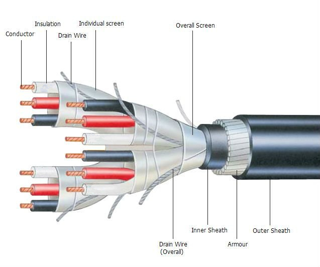
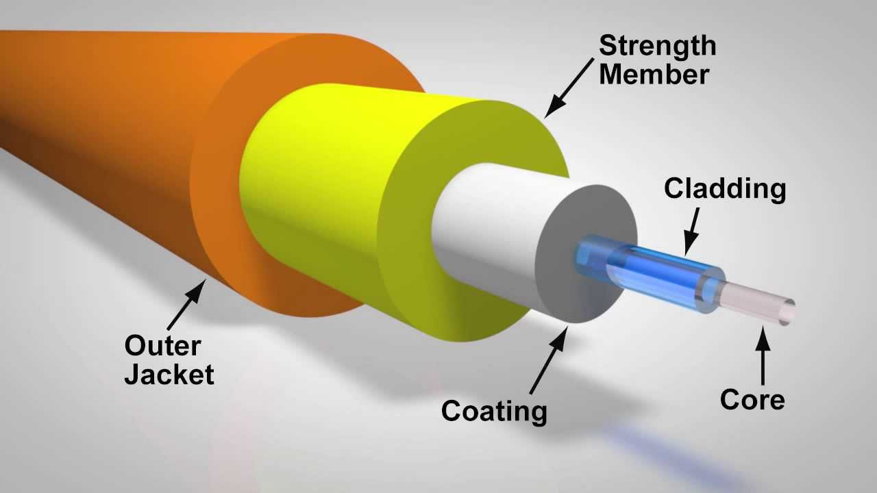
Armored fiber optic cable has some basic layers. The first layer is the outer jacket made of plastic materials. It can protect the cable from the destroy of solvent and abrasion. The second layer under outer jacket is the strength member made of armored materials, such as aluminum foil, steel and kevlar. These materials are difficult to cut, bite and burn which are great protections for the optical cable. Next is the inner jacket of fiber made of protective and flame-retardant materials to support the internal optical fibers.
armored-optical-cable-structure

Types of Armored Fiber Optic Cable
Armored fiber optic cable can be divided into indoor armored optical cable and outdoor armored optical cable according to the premises.

Indoor Armored Optical Cable
This kind of optical cable includes double and single indoor armored fiber patch cables. The double armored cable has the stainless steel wire woven and stainless steel tube. On the contrary, the single armored cable does not contain the stainless steel components. Most of the indoor armored cables are deployed for building wiring applications. You may find them in walls, between floors, in plenum air handling ducts and under data center floors, etc.

Outdoor Armored Optical Cable
There are light armored and heavy armored optical cable used for outdoor applications. The light armored cable has the protective plastic jacket with the same durability and longevity of a stainless steel cable, but its weight is much lighter. The heavy armored cable is wrapped in a wire circle which can be applied for riverbed and ocean floor.

Advantages of Armored Fiber Optic Cable
There are numerous advantages of armored fiber optic cable. The flexibility and durability of armored cable are excellent which makes it the right choice for industrial purposes. Moreover, the armor materials protect the cable from damage caused by animal, human or harsh environment, thus it can be applied to places where ordinary cables can not. The armored cable can also undergo heat and high pressure of extreme conditions. Using the armored optical cable not only ensures the high speed data transmission, but also extends the life span of cables.

Conclusion
When fiber optic cables are needed for terrible conditions, a strong protection for the cable is very necessary. Therefore, to secure the data communication, armored fiber optic cable is a good solution to make the cable free from different damages. But when you operate the armored cables, you must be careful of the freshly cut edges which are very sharp to cope with. And the budget of your project should also be taken into consideration as armored cables are generally more expensive than the common ones.

2016年6月28日星期二

What is Fiber Optic Attenuator?

In optical data communication, receiving either too much or too little optical power will cause high bit error rates. The receiver amplifier will saturate if power is excessive, or generate noise when interferes with the signal if power is insufficient. In order to solve the problem of too much optical power at the receiver, using a fiber optic attenuator is a good solution.

Fiber optic attenuator or optical attenuator is a passive device used to reduce the power level of an optical signal without appreciably distorting the waveform. To achieve power loss, technologies including air-gap, absorption, scattering, and interference filter are often used for the attenuator products. Fiber optic attenuator can be fixed, manually or electrically adjustable. Furthermore, according to different types of connectors, there are also various classifications of optical attenuators as LC, SC, ST, FC, MU or E2000, etc. This article will introduce some basic working principles and commonly used types of optical attenuators.

Working Principles
With the development of optical technologies, fiber optical attenuator has adopted many principles to help reduce optical power. Here are some of the working principles applied to the fiber optical attenuator:
    • Gap-loss Principle: Gap-loss principle uses an in-line configuration when inserting the optical attenuator in the fiber path to reduce the optical power level. The gap enables light to spread out as soon as it leaves the fiber end from the transmitter. Then some of the light will enter the fiber cladding before it reaches the receiver. However, optical attenuator using gap-loss principle is sensitive to the modal distribution, which means it should be placed near the optical transmitter. Otherwise, the attenuator will be less effective to get enough power loss if being put far away from the transmitter. This kind of problem can be avoided when using the absorptive or reflective principles.
Gap-loss Principle
    • Absorptive Principle: Absorptive principle or absorption reduces the light power by using the material in the optical path to absorb optical energy. This can be realized because optical fiber has the defect of absorbing optical energy and converting it into heat. It is both easy and effective to employ absorptive principle to obtain power loss.
Absorptive Principle
  • Reflective Principle: Reflective principle or scattering causes the signal to scatter which is also a deficiency of optic fiber. The scattered light interferes with fiber to reduce the signal power. Since the material in attenuator is used to reflect a known quantity of the signal, only a desired portion of signal can be transmitted.
Reflective Principle
Common Fiber Optic Attenuator Types
    • Fixed Attenuator: Fixed attenuator is able to deliver a precise power output when the desired level of attenuation is determined. It is usually applied to balance power between fibers and multifiber systems and reduce receiver saturation. Fixed attenuator is typically available in plug and inline styles for single-mode applications. Inline type looks like the ordinary fiber patch cord with the termination of two connectors. Plug type has a bulk head fiber connector with a male end and a female end.
fixed-fiber-optic-attenuator
  • Variable Attenuator: Variable attenuator delivers a precise power output at multiple decibel loss levels with flexible adjustment. The attenuation is easily modified to any level by simple adjustment controls. Variable attenuators can be further categorized as stepwise variable attenuator and continuously variable attenuator. The former changes the attenuation of signal in known steps such as 0.1 dB, 0.5 dB or 1 dB for multiple power sources applications. The latter allows attenuation to be changed on demand without any interruption to the circuit in uncontrolled environments where the input or output needs continuous change.
variable-fiber-optic-attenuator

Conclusion
Fiber optic attenuator is an essential component for reducing optical power in data transmission. Signals achieve a more precise power level with the help of optical attenuators. According to different applications, you’d better choose the most appropriate type of optical attenuators for your system. Hope this article can provide some help for your future selection of optical attenuators.

2016年6月24日星期五

Overview of Fiber Optic Loopback

When testing the transmission equipment, loopback device is often used as the testing tool. It is known as the routing of electronic signals, digital data streams, or flows of items back to their source without intentional processing or modification. Loopback is widely used for various applications. In terms of telecommunication, loopback is a hardware or software method to feed a received signal or data back to the sender. It is very useful for solving physical connection problems. In this article, the author will especially emphasize the using of loopback in fiber optic communication. Hope it can provide some help for your application!

Types of Fiber Optic Loopback
So, what is exactly the fiber optic loopback? By diagnosing the problems of optical equipment, fiber optic loopback provides an easy way to test the performance of the optical network devices. Generally, fiber optic loopback cable and fiber optic loopback module are both fiber optic loopbacks. Fiber optic loopback cable is the traditional fiber optic loopback with a visible cable. It is equipped with two fiber optic connectors on each end of the cable. When sticking the connectors together, the cable will shape like a loop. As for fiber optic loopback module, the biggest difference is that it has a enclosure to protect the inside cable. And the looped space is reduced for an easier usage and economic package.

fiber optic loopback
You may find that loopback also has different types of optical connectors and fibers. Categorized by connectors, fiber optic loopback has SC, LC, MTRJ, E2000 types, etc. LC fiber optic loopback complies with the RJ-45 style interface. Having a low insertion loss, low back reflection and high precision alignment, LC fiber optic loopback is widely used all over the world. Another frequently used type is SC fiber optic loopback. Its connector is compliant to IEC, TIA/EIA, NTT and JIS specifications. Now it is the most popular loopback with low cost but high performance. In addition, to separate by fiber types, single-mode loopback (9/125) and multimode loopback (50/125, 62.5/125)  are deployed for the application.

Fiber Optic Loopback Testing
Typically, a loopback test is a test in which a signal is sent from a communication device and looped back to the device as a way to determine whether it is functioning well or as a way to troubleshoot a defective node in the network. As for fiber optic loopback testing, optical loopbacks are used to verify the operational reliability of the device. Using fiber optic loopback cable or fiber optic loopback module for data transmission, the signal emitted by the device is looped from the transmit (Tx) end of an active component back to the receive (Rx) end of the same component.

Application
When it comes to practical application, fiber optic loopback test is often employed for checking fiber optic transceivers. Since transceiver has two ports for receiving and transmitting the light signal, it is necessary to test the ports to see whether they are still under operation. Thus, fiber optic loopback test is the most convenient way for transceiver maintenance. The testing process is by routing the laser signal from the transmitter port back to the receiver port. Then the transmitted pattern is compared with the received pattern to make sure they are identical and have no error.

Conclusion
In a word, fiber optic loopback is basically a patch cord used for fiber optic loopback testing. Similar to other cables, it also has multiple classifications of fiber types, connector types for different needs. The deployment of fiber optic loopback components has greatly saved the trouble for device checking. There is no doubt that using fiber optic loopback is an effective method in fiber optic communication.

Getting to Know PoE Network

With the rapid development of networking, a variety of technologies have been created. In 2003, PoE (power over Ethernet) network technology has been standardized. And it is now widely used for wireless LANs (local area networks), IP cameras and VoIP (voice over Internet protocol) phones. PoE allows cables to carry both electrical power and data signal to devices. Electrical current will support the operation of devices which greatly reduces the amount of wires used for network installation. Thus, the emergence of PoE network is absolutely a good news for the development of cost-efficient networking. Next, more information about PoE network will be discussed in the following paragraphs.

PoE network

Operating Principle of PoE
There are three basic components in PoE system - PSE, PD and Ethernet cable. PSE (power sourcing equipment) like PoE switch is the device used for delivering power to cable. PD (powered device) is the device used for receiving power from the cable. And cable will help transmit the electrical power and data signal. The electrical current will first go into the cable at the PSE end, and then come out at the PD end. Since it is the transmission of electric signal, PoE is only available to twisted pair Ethernet cabling. Also, the current is separated from data signal so that neither of them interferes with the other.

Advantages of PoE

Using the PoE network has many advantages:
  • Flexibility Because devices like IP cameras and wireless access points are not permanently attached to an electrical outlet, they can be located regardless of area restriction. Reinstallation is also easy to implement.
  • Safety PoE network is designed to be safe enough to protect network equipment from overload, underpowering, or incorrect installation.
  • Dependability PoE power comes from a central and universally compatible source instead of a collection of distributed wall adapters. And an uninterruptible power supply is backing up the PoE network for a more stable operation.
  • Scalability Owing to the electrical power available on PoE network, the installation and distribution of network connections are more simple and effective.
Applications of PoE
VoIP phones, WLAN, RFID (radio frequency identification), security cameras or access control devices are major applications for PoE network. Using PoE network enables the VoIP to receive uninterrupted power through the network, without the need for an AC outlet for each phone. And WLAN access point can be placed in different locations such as ceilings, hallways, lobbies without electrical outlets. Likewise, PoE allows RFID readers to be strategically situated in locations that optimize effectiveness. And it is cheaper to use PoE network for security cameras or access control devices on ceilings, hallways, lobbies, or outdoor areas.

Conclusions
To sum up, the advent of PoE has greatly improved the effectiveness of network. Equipment are able to be located at any place due to the power availability. And a large number of cost will be saved by eliminating unnecessary wires. This article only gives a brief introduction to the PoE network. There still has a lot for us to explore.

Cable Shielding of Twisted Pair


For the purpose of providing a reliable connection between electronic devices, choosing a proper shielded twisted pair cable is essential to the network using copper cables. EMI (electromagnetic interference) is a disturbance in twisted pair cables. It affects the performance of an electrical circuit by electromagnetic induction, electrostatic coupling, or conduction. But with the help of cable shielding, cables can be immune to the disturbance and keep a stable connection. And this article will present some knowledge about cable shielding. Hope you can find it useful.

STP vs. UTP
Before getting to know cable shielding, you may wonder about the real difference between shielded twisted pair (STP) and unshielded twisted pair (UTP). As their names suggest, STP has a shield that works as a guard and drains the induced current surges to earth. Yet UTP has no cable shield with such a function. But the shortcoming of STP cables is the extra shielding cost added to an installation. Typically, STP cables are more expensive than UTP cables. And due to the stiffer and heavier shielding, coping with STP cables is more difficult. But if you pursue a higher performance, STP will be a preferable choice.

Types of Shields
There are mainly two types of shields: braided shield and foiled shield. Braided shield is made up of woven mesh of bare or tinned copper wires. It has better conductivity than aluminum and more bulk for conducting noise. An easier attachment with connectors can be achieved by crimping and soldering the braid. However, braided shield does not possess 100% coverage. It usually provides 70% to 95% coverage according to the tightness of weave. But as a matter of fact, 70% coverage is always sufficient if cables are fixed. Another shielding is foiled shield. This type of shielding uses a thin layer of aluminum and has a 100% coverage around the conductors. But the drawback is that its conductivity is lower than copper braided shield.
braided shield and foiled shield


Different Constructions of Shielding
Today, people will use acronyms to name different shielding constructions. Take U/FTP as an example, the first letter “U” represents the outer shield or overall shield of cable, and the followed letter “F” represents the individual shield under the overall shield of each twisted pair or quad.

shielding construction

Here are some commonly used shielding constructions:

1) Individual Shield
U/FTP is the typical individual shielding using aluminum foil. This kind of construction has one shield for each twisted pair or quad above the conductor and insulation. Individual shield especially protects neighboring pairs from crosstalk.

2) Overall Shield
F/UTP, S/UTP, and SF/UTP are overall shielding with different shield materials. Overall shield refers to the entire coverage around the whole cable. This type of shielding helps prevent EMI from entering or exiting the cable.

3) Individual and Overall Shield
F/FTP, S/FTP, and SF/FTP are individual and overall shield. This type of construction has both layers of shielding. And its immunity to EMI disturbance is greatly improved.

Meanings of the abbreviated letters: 
U = unshielded 
F = foiled shielding 
S = braided shielding 
TP = twisted pair

Applications
As for the application in 10GBASE-T Ethernet, UTP, U/FTP, F/UTP, F/FTP and S/FTP are often used. But their practicable cable categories are varied from cat 6/6a to cat 7/7a. When twisted pair cable is deployed for 40GBASE-T Ethernet, U/FTP, F/UTP, F/FTP, S/FTP are applied under cat 8/8.1/8.2.

Conclusion
Adopting twisted pair cable shielding is an effective method to prevent EMI from interfering signal transmission. And there are different shielding constructions for you to choose. Of course, using twisted pair without cable shielding is also feasible if your budget is limited. Wish you find the most suitable twisted pair cable for your project!

2016年6月16日星期四

Overview of PON Network

PON has now became a popular network technology all over the globe. It first came in to being in 1995. The International Telecommunication Union (ITU) standardized two initial generations of PON - APON and BPON. And the advancement of PON network has never stopped. Until now, the recent PON standard of NG-PON2 has been put forward in 2015. With the maturity of PON, people are more easily accessible to networks today. But what does PON exactly mean? What’s the composition of PON network? The following part will give you the answer.

PON, also known as passive optical network, is a technology in telecommunication that implements a point-to-multipoint (P2MP) architecture. Unpowered fiber optic splitters are used to enable a single optical fiber to serve multiple end-points such as customers instead of providing individual fibers between the central office (hub) and customer. According to different terminations of PON, the network system can be divided into fiber-to-the-home (FTTH), fiber-to-the-curb (FTTC), fiber-to-the-curb (FTTB), etc. To be specific, a PON is made up of an optical line terminal (OLT) at the service provider’s hub and a number of optical network units (ONUs) or optical network terminals (ONTs) near end users. And “passive” is just used to describe that no power requirement or active electronic component is included for transmitting signals in the system.

PON

Here are some types of PON that have been used throughout the years:
1) APON
Its full name is asynchronous transfer mode (ATM) passive optical network. As the original PON system, APON uses ATM technology to transfer data in packets or cells of a fixed size. In APON, downstream transmission is a continuous ATM stream at a bit rate of 155 Mbps or 622 Mbps. Upstream transmission is in the form of bursts of ATM cells at 155 Mbps.

2) BPON
BPON, also known as broadband PON, is the improved version of APON. It adopts wavelength division multiplexing (WDM) for downstream transmission with the transmission rate up to 622 Mbps. It also provides multiple broadband services such as ATM, Ethernet access and video distribution. Today, BPON is more popular than APON.

3) EPON
EPON or Ethernet PON uses the Ethernet packets instead of ATM cells. Upstream and downstream rates of EPON are able to achieve up to 10 Gbps. It is now widely applied to FTTP or FTTH architecture to serve multiple users. With the advantages of scalability, simplicity, multicast convenience and capability of providing full service access, many Asian areas adopt EPON for their networks.

4) GPON
Gigabit PON is the development of BPON. It supports various transmission rates with the same protocol. The maximum data rate of downstream is 2.5 Gbps and upstream is 1.25 Gbps. It is also widely used for FTTH networks. But compared with EPON, its burst sizes and physical layer overhead are smaller.

Advantages of PON
  • Low cost, simple maintenance, flexible extensibility and easy to upgrade. And no need for power during transmission saves a lot for long-term management.
  • Using pure media network avoids the interference of lightning and electromagnetism. Thus PON network is suitable for areas under harsh conditions.
  • Low occupancy of central office resources, low initial investment and high rate of return.
  • As the P2MP network, PON is able to provide a large range of service to plenty of users.
Conclusion
PON network is for sure an effective solution for multiple network users. EPON and GPON are the most commonly deployed PON systems at present. Since people have been seeking for higher bandwidth provisioning, the capability of transmission will be greatly improved in the near future.

2016年6月15日星期三

Introduction to Categories of Twisted Pair

As one of the oldest types of cable ever invented, twisted pair cabling was first developed by Alexander Graham Bell in 1881. Since then, it has been widely deployed for telephone line network in America. Nowadays, the application of twisted pair has been extended worldwide mainly for outdoor land lines offering telephone voice service.

Generally speaking, twisted pair cabling is a kind of copper wiring that two conductors of a single circuit are twisted together. The purpose of using twisted pair is to offset electromagnetic interference (EMI) from external sources to stop degrading the performance of circuit. Also, different standards of twisted pair are specified into various categories as cat 1, cat 2, cat 3, cat 4, cat 5/5e, cat 6/6a, cat 7/7a, cat 8/8.1/8.2. And this article will give a brief introduction to some of the above categories.

twisted pair


Different Categories of Twisted Pair

1) Cat 5/5e
Cat 5 twisted pair cable is often used for structured cabling of computer networks. It is available to 10/100 Mbps speeds at up to 100 MHz bandwidth. However, it is now considered to be obsolete and replaced by cat 5e (enhanced). Cat 5e is one the most commonly used twisted pair cables at present. The biggest distinction between cat 5 and cat 5e is that cat 5e has a lower cross talk and its transmitting speed can reach up to 1000 Mbps.

2) Cat 6/6a
As a substitute of cat 5/5e, cat 6 twisted pair is applied to Gigabit Ethernet and other network physical layers. It supports up to 10 Gbps speed at 250 MHz. When used for 10GBASE-T applications, cat 6 has a reduced maximum length from 37 to 55 meters. But cat 6a (augmented) has been evolved to perform at up to 500 MHz, thus the maximum cable distance is longer than cat 6 of up to 100 meters.

3) Cat 7/7a
Cat 7 is the standard for twisted pair cabling used for 1000BASE-T and 10GBASE-T networks. It provides performance of up to 600 MHz with a maximum length of 100 meters. As for the cat 7a (augmented) cable, it has a higher frequency of 1000 MHz. Results show that it may be possible to support 40 GbE or even 100 GbE at a very short length.

4) Cat 8/8.1/8.2
Cat 8 is the USA standard specified by ANSI/TIA while cat 8.1 and cat 8.2 are specified by ISO/IEC for global application. All these three kinds of cat 8 twisted pairs are used for 25GBASE-T and 40GBSE-T at the maximum frequency of up to 2 GHz. Except cat 8 adopts cat 8 links, cat 8.1 uses class I links and cat 8.2 uses class II links. The key difference between class I and class II is that class II allows three different styles of connectors to be not compatible with one another, or with the RJ45 connector.

Conclusion
Twisted pair cables have been classified into different grades called categories. These standards especially formulate the data capacity of the cable. Higher categories are more expensive than lower ones, but most of cost is actually spent on labor force for installing the cables. And twisted pair cables under cat 5 are not recommended now. Higher categories are the future trends for network cabling.

Take Cable Management Seriously

In a data center, it is common to see messy cables all over the place. Finding out the right cable becomes a nightmare. However, there are also good examples for well-organized cables that eliminate all the redundant operations due to cable mess. This is the magic of cable management. Typically, cable management is a solution used for the installation of equipment in order to secure cables for electrical services. An orderly data center will greatly enhance the working efficiency and ordinary people are more willing to work in a tidy environment. Therefore, cable management is very necessary for data center cabling.

cable managemet

Benefits of Cable Management
With the help of cable management, there are many advantages that facilitate the work in data center:

1) Ease of Cable Connection
A good cable management can not only provide access to cables but also to devices they are connected to. If cables are tangled together, it will increase the difficulty for handling devices. And working hours are extended for a simple task. But if your cables are well-managed, the connection between cables and devices will be clear to see so as to finish work in a shorter time.

2) Avoid the Risk of Fire
If cables are not under maintenance for a long time, sparks will be easily caused in tangled cables. And the worst result will be a fire. In addition, when a person passes by the cable mess, he is more likely to be stumbled by the cables. Thus the risk of fire is also immensely increased. To avoid such situation, cable management takes an important role for fire safety.

3) Convenient Troubleshooting
While doing the routine troubleshooting in data center, cable testing is one of the steps. However, a huge amount of messy cables makes such a simple task into a complicated one and you have no idea how long it will take to finish the job. But thanks to cable management, you can easily maintain and change cables in order. The process is more convenient if cables are organized well.

Suggestions for Good Cable Management
To achieve a good cable management, here are some useful suggestions:

1) Let in Airflow
Enough airflow will reduce the temperature of surroundings and components for lowering the risk of fire. But the tangled cables will block the air from flowing. Therefore, sorting out the cables to leave enough space for air flowing is very essential. Also, fans can be used as a way to create sufficient airflow to cool down the temperature more promptly.

2) Clean the Dust
A good cable management is always along with dust cleaning. If too much dust enters through the components, the efficiency of devices will be influenced. But the best part for a good cable management is that the open surfaces exposed to dust are greatly reduced, so the cleaning process is a lot easier.

3) Neat Appearance
First impression is always important for the judgment of a good cable management, thus keeping a nice appearance is necessary. The basic rule of managing cables is to make them in a neat order. Then a little imagination can be added to make the appearance more creative.

4) Use Proper Tools
Proper tools are needed for cable management because they can improve the efficiency of your work. Tools like cable wrap, screwdriver, wire scissors, pliers, cable ties, rubber band, etc. are recommended. These instruments makes the process more convenient and easier.

Conclusion
You may think of cable management as a tedious and time-consuming task. But as for the long-term benefit, cable management can prevent device from damage and save time for routine maintenance. Thus better take it seriously for the best of your work in data center.

2016年6月9日星期四

Have You Chosen the Right Cables Ties?


You can frequently find racks, frames or panels in the cabling system. They are necessary components for cable management. However, sometimes you may easily forget about a small but helpful tool for cable management - that is cable tie. People’s first impression about cable tie is always a self-locking and colorful plastic strip. They think cables ties are pretty much the same. Seldom have they considered about whether they are choosing the right cable ties or not. In fact, cables ties have many different distinctions in construction, material, color, size and some special features. So do you want to know if your selection is right? Don’t worry. The following parts will give the explanation.

cable ties

Cable ties have to be able to meet the most varied demands these days as they are used in the widest range of operations – from the simple bundling of cables with cable ties to the absolutely specific use of cable ties under extreme conditions. Thus, many factors are taken into consideration during the design of cable ties.

Construction

Cable ties can be classified as either one-piece or two-piece construction. One-piece cable ties typically have a plastic locking device molded into the head of the tie. The locking device ratchets the notched strap to tighten and lock. This design has a lower cost of manufacturing and is used for general applications around home or office. Compared to one-piece cable ties, two-piece cable ties are with higher performance. They consist of a stainless-steel locking device embedded into the head of the tie, and a smooth locking strap. This design offers high tensile strength, and resistance to mechanical and environmental stress for applications that require greater performance than what a general cable tie offers. In addition, the smooth, infinitely adjustable strap also allows for the exact bundled tightness. The head of the two-piece cable tie engages the strap when installed, and permanently locks in place. With a lower profile and smoother cross-section, the uniform cross-section distributes stress across the strap more evenly than with one-piece cable ties. Thus, the two-piece cable ties are more resistant to brittleness and breakage in harsh environments, particularly appropriate for harsh conditions, such as ultraviolet exposure, extreme temperature, and exposure to moisture or chemicals, as well as for applications where retrofitting is not an option.

Material

The material design of different cable ties also needs to consider for different applications, such as occurring indoors or outdoors; the environment’s temperature range; the presence of moisture, chemicals and radiation; flammability issues; and cost. Cable ties are available in a wide range of materials, each with its own specific properties. Among them, the most common type is nylon cable ties. Nylon ties can offer good resistance to weather and ultraviolet rays in lower temperatures. In addition, for applications in harsher environments that require extra durability in the face of heat, chemicals and other corrosive elements, there are stainless-steel cable ties.
Color
The most commonly used cable ties are white and black. But colorful cable ties are also popular with users. These cable ties with rainbow colors are very useful when you are trying to color-code your cables, or just want to match the ties to your equipment. Moreover, you can use different cable ties to mark different cables bunch which is convenient for cable management.

Size

When using cable ties, you should also consider the size and shape. First, be sure to measure the diameter of the cable bundle you’ll be tying and decide the length. In general, to buy cable ties with a little longer length is better. Because no one wants to find out at the last minute that the cable ties are too short to use. In addition to length, width or shape are also important considerations to choose optimal cable ties for your cable bunch.

Special Features

Though the standard-design cable ties can meet most of our requirements, sometimes, we still need something special for special applications. For instance, most cable ties lock permanently, but sometimes, we would prefer to looking for a solution that cable ties can be undone without actual cutting. Then, releasable cable ties have been launched in the market. In a releasable cable tie, the built-in locking tab can actually be disengaged, allowing the tail end of the tie to be pulled free from the head. Releasable cable ties tend to cost a little more than the standard type, but they save money and are more eco-friendly in the long run because you can reuse them over and over instead of just throwing them away. Additionally, for different special applications, there are mounted head cable ties, marker ties, etc.

Conclusion

It is very unprofessional to use random cable ties for your cable management. Knowing the secrets about cable ties can lead you to choose the matching cable ties for your applications. This will greatly reduce the unnecessary problems during actual practice. Actually, no matter cable ties or other assembles, each component of cabling system should not be underestimated. The right selection will greatly increase the efficiency of a cabling system.

Introduction to Fiber Optic Pigtails

During the process of fiber optic cable installation, cable connection is important to ensure the low attenuation and low return loss of signal transmission between cable and equipment. And fiber optic pigtail is a commonly used component for the connection of optical network. It is a piece of cable terminated with fiber optic connectors at one end and no connector at the other end. In this way, the connector side can be linked to the equipment and the other side can be fused with optical cable fibers. This article will emphasize on the types of fiber optic pigtails and their applications.

Here are two classifications of fiber optic pigtails. Firstly classified by connectors, fiber optic pigtails has seven types including E2000, LC, SC, ST, FC, MU and MTRJ. Secondly classified by fibers, fiber optic pigtails has two types as single-mode and multimode.

Classification of Connector

LC fiber optic pigtailSC fiber optic pigtail1)LC fiber optic pigtail uses the LC connector developed by Lucent Company. LC connector is now one of the most popular connectors in the world. A 1.25mm ceramic ferrule makes LC fiber optic pigtail a better choice for low cost but high precision signal transmission.

2) SC fiber optic pigtail uses the SC connector developed by Nippon Telegraph and Telephone. SC connector has a ceramic ferrule of 2.5 mm. Its light weight and cost-effective features enable different applications of SC fiber optic pigtail.


ST fiber optic pigtail3)ST fiber optic pigtail uses the ST connector developed by American Telephone & Telegraph. ST connector has a 2.5mm bayonet-styled ferrule. It is one of the eldest generations of fiber optic connectors. But it is still used for many fiber optic applications, especially for multimode fiber optic communications.


FC fiber optic pigtail4)FC fiber optic pigtail uses the FC connector developed by Nippon Electric Company. The connector features the screw type structure and high precision ceramic ferrule. FC fiber optic pigtail is usually used for general fiber optic applications.


Classification of Fiber Types

Single-mode fiber and multimode fiber are both used for fiber optic pigtails. The single-mode fiber optic pigtail has a 9/125 micron core size. SC, LC, ST, FC and E2000 connectors are all fit for this kind of fiber. As for multimode fiber optic pigtails, there are two different core sizes. One is 62.5/125 micron of OM1, and the other is 50/125 micron of OM2, OM3, OM4. SC, LC, ST, FC connectors are adaptable to multimode fiber optic pigtails.

Applications

Fiber optic pigtail sometimes has multiple fiber strands, including 4 fibers, 6 fibers, 8 fibers, 12 fibers, 24 fibers, 48 fibers and so on. This helps the effective interconnection and cross-connect in various applications. Since fiber optic pigtail supports fusion splicing, it is often used with devices like optical distribution frames, splice closures and cross cabinets.

Conclusion

In summary, fiber optic pigtail is a cable that only one end is terminated with connectors. The other end can be melted with optical fiber for a permanent connection. You may choose the adaptable fiber optic pigtail from the perspective of connector types, fiber types, strand numbers, etc. Hope this article can provide a little help.

2016年6月8日星期三

Suggestions for Solving Unsupported Transceiver Errors


The unsupported transceiver errors may arise at any time of your work. Though this situation is the least you want to see during work, you must be enough prepared to solve issues in time. To deal with the errors is now an essential part to keep good running of devices. And different vendors will have tips to solve errors for their own products. But are there any suggestions for general issues? The answer is yes. This article will give some advice for how to deal with unsupported transceiver errors on ordinary occasions.

Unsupported Transceiver Errors

Suggestions
1)Check the error message first before actually deal with the problem. Different ways to address the errors are depending on the message you receive. Here is an example, when you receive this message, “3750e-sw1(config)#service unsupported-transceiver [1]”, the error may result from the false customer installation or a defective product. Thus, error message is a good source to decide your next step.

2)An uncertified transceiver will cause errors under most cases. When the third-party device does not come from a channel partner, problems may also arise. It is not that easy to address router issues if the transceivers is required to be made from the same manufacturer. But specialists may turn to hack codes to solve the problem.

3)Hidden commands of some devices may also cause errors. The message will go like “service unsupported transceiver”. But it allows other transceivers as an option for you to decide whether the transceiver should be replaced.

4)Before removing the transceiver to solve a third-party error, you can look up other options first. Because sometimes the third-party transceiver can provide significant savings for you. Perhaps one of the savings will help settle the problem.

About Third-Party Transceivers
Although you may encounter the unsupported errors when using the third-party transceiver, it still has some advantages. The major benefit is the cost which is much lower than the cost of original transceivers. Since the cost of transceiver takes a huge part of the entire system cost, reducing the investment on transceiver can greatly save expenses for better designs.

Also, the compatibility of third-party transceivers has been greatly increased thanks to the fully specified international standards. The risk of incompatibility is much lower, and there is no need to worry about buying a transceiver from formal vendors. For instance, FS.COM is one of the reliable manufacturers that provides cost-effective third-party transceivers, and all of the transceivers are 100% compatible to any named brands like Cisco, Juniper, Arista and so on.

Conclusion
Anyway, in order to avoid unsuspected transceiver errors, the fundamental aim is to make sure that the transceiver completely complies with IEEE and MSA standards. Understanding the hidden commands can also help you find out the source of error. So long as you follow the above suggestions, most of the problems can be solved in a short time. The purpose of dealing with the errors is all about getting good results, and your working efficiency will also be improved if there is no problem with the devices.

2016年6月2日星期四

Do You Know About Fiber Optic Splitter?

In today’s optical network topologies, the advent of fiber optic splitter is significant in helping users maximum the performance of optical network circuits. Fiber optic splitter, or sometimes called as beam splitter, is a passive optical component that can split an incident light beam into two or more light beams, and vice versa. The device contains multiple input and output ends. Whenever the light transmission in a network needs to be divided, fiber optic splitter can be implemented for the convenience of network interconnections.


How Does Fiber Optic Splitter Work?
As for the working principle of fiber optic splitter, it can be generally described in the following way. When the light signal transmits in a single-mode fiber, the light energy can not entirely concentrated in the fiber core. A small amount of energy will be spread through the cladding of fiber. That is to say, if two fibers are close enough to each other, the transmitting light in an optical fiber can enter into another optical fiber. Therefore, the reallocation technique of optical signal can be achieved in multiple fibers. And this is how fiber optic splitter comes into being.

Classification of Fiber Optic Splitter
At present, there are two types of fiber optic splitters. One is known as PLC (planar lightwave circuit) splitter, and another one is known as FBT (fused biconical taper) splitter.

1) PLC splitter divides the incoming signal into multiple outputs by using an optic splitter chip. One optic splitter chip is able to achieve at most 64 ends. PLC splitter is usually used for larger applications. The losses of PLC splitter are not sensitive to the wavelength, which satisfies the need for multiple wavelengths transmission. PLC splitter’s configuration is compact and its size is small, thus the installation space can be greatly saved.

2) FBT splitter is fused with a heat source similar to a one-to-one fusion splice. Fibers are stretched under a heating zone to form a double cone. The cost of FBT splitter is lower due to the commonly used materials, and the splitting ratio is adjustable. But the losses are sensitive to wavelengths. Device should be chosen according to wavelengths. And it is unable to offer the uniform spectroscopy.

Applications
1) Passive monitoring application of fiber optic splitter is used for the maintenance of long-haul network, cable TV ATM circuit or local area/metro area network. The splitter taps into a small percentage of optical traffic. Majority of the signal arrives its destination, but a small percentage is directed to a local access port. The application can be done by manual operation for troubleshooting purposes or by connecting the splitter to a network monitoring system for ongoing maintenance and performance assessment.

2) Fiber optic splitter can also be used for FTTx/PON application. This enables to reduce the physical fiber usage or the basic quantity of required fibers. A single fiber can be split into many branches to support multiple end users. The strain on the fiber backbone can be greatly decreased through the application.

Conclusion
To sum up, fiber optic splitter provides a solution for improving the efficiency of optical infrastructures. PLC splitter and FBT splitter are varied in different aspects, hence choosing the right type of splitter for your network is also important. FS.COM provides all the above fiber optic splitters. Please visit FS.COM for more information.

2016年6月1日星期三

Comparison Between CWDM & DWDM Technology


For a better signal transmission in fiber-optic communication, different kinds of technologies are applied to the industry. Wavelength-division multiplexing (WDM) is one of the commonly used technologies which multiplexes a number of optical carrier signals onto a single optic fiber by using different wavelengths of laser light. That is to say, WDM enables two or more than two wavelength signals to transmit through different optical channels in the same optical fiber at the same time.
WDM

In the WDM system, there are two types of divisions - CWDM (coarse wavelength division multiplexing) and DWDM (dense wavelength division multiplexing). They are both using multiple wavelengths of laser light for signal transmission on a single fiber. However, from the aspects of channel spacing, transmission reach, modulation laser and cost, CWDM and DWDM still have a lot of differences. This article will focus on these distinctions and hope you can have a general understanding about CWDM and DWDM technology.

Channel Spacing
As their names suggest, the words “coarse” and “dense” reveal the difference in channel spacing. CWDM has a wider spacing than DWDM. It is able to transport up to 16 wavelengths with a channel spacing of 20 nm in the spectrum grid from 1270 nm to 1610 nm. But DWDM can carry 40, 80 or up to 160 wavelengths with a narrower spacing of 0.8 nm, 0.4 nm or 0.2 nm from the wavelengths of 1525 nm to 1565 nm (C band) or 1570 nm to 1610 nm (L band). It is no doubt that DWDM has a higher performance for transmitting a greater number of multiple wavelengths on a single fiber.
CWDM-VS-DWDM

Transmission Reach
Since the wavelengths are highly integrated in the fiber during light transmission, DWDM is able to reach a longer distance than CWDM. The amplified wavelengths provide DWDM with the ability of suffering less interference over long-haul cables. Unlike DWDM system, CWDM is unable to travel unlimited distance. The maximum reach of CWDM is about 160 kilometers but an amplified DWDM system can go much further as the signal strength is boosted periodically throughout the run.

Modulation Laser
CWDM system uses the uncooled laser while DWDM system uses the cooling laser. Laser cooling refers to a number of techniques in which atomic and molecular samples are cooled down to near absolute zero through the interaction with one or more laser fields. Cooling laser adopts temperature tuning which ensures better performance, higher safety and longer life span of DWDM system. But it also consumes more power than the electronic tuning uncooled laser used by CWDM system.

Cost
Because the range of temperature distribution is nonuniform in a very wide wavelength, so the temperature tuning is very difficult to realize, thus using the cooling laser technique increases the cost of DWDM system. Typically, DWDM equipment is four or five times more expensive than CWDM equipment.

Conclusion
CWDM and DWDM are both coming from the WDM technology that is capable of conveying multiple wavelengths in a single fiber. But with different characteristics, people should think twice before choosing the CWDM or DWDM system. CWDM usually costs less but its performance is far behind DWDM. Both your requirements and budget need to be taken into consideration. Moreover, the WDM products including CWDM mux/demux module, DWDM mux/demux module and optical splitter are highly welcome in the market.

Article source: http://www.fiber-optic-cable-sale.com/comparison-between-cwdm-dwdm-technology.html.