2017年2月21日星期二

Suggested 100G QSFP28 Transceiver Solutions for Data Centers

In recent years, QSFP28 transceiver module has upgraded the 100G market which can support the data transmission mode of 4×25G. Currently many data centers have already adopted QSFP28 transceivers for 100G migration. Of course, there are many other types of transceivers can transfer the 100G network, but QSFP28 modules are still considered to be the optimal choice. This post is going to present some useful 100G QSFP28 transceiver solutions for data centers. Maybe one of them is exactly what you need.

Basics of QSFP28 Optical Transceiver
QSFP28 transceiver is designed for high-density and high-speed for applications in telecommunications. The transceiver offers four channels of different signals with data rates ranging from 25 Gbps up to potentially 40 Gbps, and meets 100 Gbps Ethernet (4x25 Gbps) and 100 Gbps 4X InfiniBand Enhanced Data Rate (EDR) requirements. QSFP28 optical transceiver has various advantages. It has a smaller size than other 100G modules, thus it is ideal for high-density ports on the switch. Power consumption of QSFP28 transceiver is usually the lowest of less than 3.5W. In addition, QSFP28 increases the transmission capacity of every lane from 10G to 25G, which can save much cost for each bit.

QSFP28 Transceiver Solutions
QSFP28 transceivers can be categorized into several types based on different IEEE (Institute of Electrical and Electronics Engineers ) or MSA (Multi-source Agreement) standards.

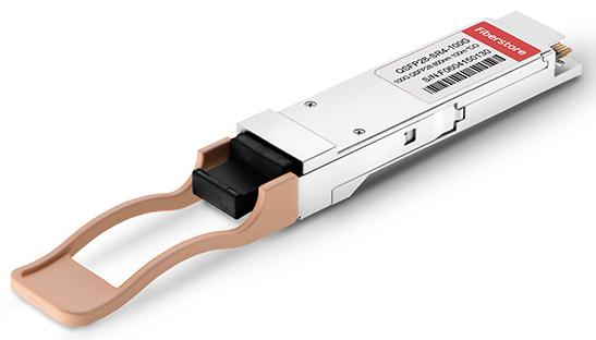
100GBASE-SR4 is the IEEE standard for 100G QSFP28 that supports short distance over multimode. It can reach 100G transmission up to 70m over OM3 and 100m over OM4. With the MTP/MPO interface, 100GASE-SR4 QSFP28 transceiver supports four lanes of 25G dual way transmission over eight fibers.
qsfp28-sr4

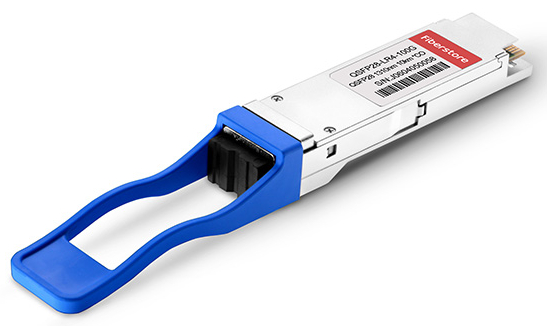
100GBASE-LR4 is also the IEEE standard for QSFP28 module but supports long distance transmission for the maximum of 10km over single-mode fiber. 100GBASE-LR4 QSFP28 is special for adopting the WDM technologies for four 25G lanes transmission over four different wavelengths. In addition, its duplex LC interface supports the 100G dual-way transmission.
qsfp28-lr4

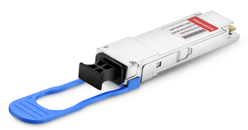
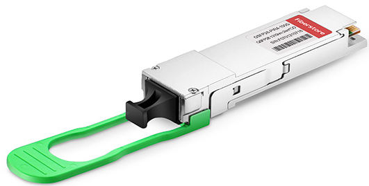
100GBASE-PSM4 is the standard defined by MSA for the point-to-point 100G link over eight single-mode fibers reaching the length of up to 500m. 100GBASE-PSM4 QSFP28 transceiver uses four identical and independent lanes for each signal direction with each lane carrying a 25G optical transmission. With the MTP/MPO interface, optical fiber ribbon cables with MTP/MPO connectors can be plugged into the QSFP28 module.
qsfp28-psm4

100GBASE-CWDM4 standard was released by CWDM MSA to support 100G network for up to 2km. It uses the CWDM technology to reduce the transmission on 8 fibers (4 optical transmitters and four optical receivers) into 2 fibers. This transceiver is similar to 100GBASE-LR4 QSFP28 but has a shorter transmission range and lower cost.
qsfp28-cwdm4

Conclusion
In a word, QSFP28 modules are suggested transceiver solutions for upgrading the data center 100G network. The 100GBASE-SR4, 100GBASE-LR4, 100GBASE-PSM4, and 100GBASE-CWDM4 QSFP28 transceivers mentioned above are the most popular ones to ensure the high-speed data transmission at either short or long distance. FS.COM offers both generic and compatible QSFP28 modules according to your demands. Other than QSFP28 transceivers, there are also many other types of 100G transceivers, such as CFP, CFP2, CFP4, CXP transceivers. For more information, please kindly visit FS.COM or contact us directly via sales@fs.com.

2017年2月16日星期四

How to Clean a Fiber Optic Transceiver?

To ensure the high performance of optical data transmission, fiber optic cleaning is regarded as an essential way to get rid of the contaminants on devices. Fiber optic connectors are often recommended to be cleaned on a regular basis. Apart from the connectors, other devices such as fiber optic transceiver, optical adapter should also be cleaned when they are being polluted. This post will focus on introducing the proper method of cleaning fiber optic transceivers.

How to Find a Contaminated Optical Transceiver?
Compared with connectors, transceiver modules seem to have a smaller chance to be contaminated. Therefore, fiber optic transceivers should only be cleaned when problems occur. Generally, if signal output from the transceiver is still false or in low-power after cleaning the connectors, you can clean the fiber optic transceiver instead to solve the issue. Common contaminant in optical transceivers is the debris or particles coming through the contact with optical connector ferrules. The following picture shows the comparison of dirty and clean interfaces of transceivers under the digital microscope.
fiber optic transceiver contaminants

Cleaning Tools
Air duster and lint-free swab are the major cleaning tools for fiber optic transceivers. Air duster uses the clean dry air to blow any dust and debris out of the transceiver. Lint-free swab is special for not leaving any lint in the transceiver interface after cleaning.
cleaning tools

Things to Note Before Cleaning
A safe operation is very important to protect yourself from unnecessary accidents. Before starting the cleaning process, here are some precautions for you to note.
  • Always handle optical modules in an ESD (electro-static discharge) safe area using the proper safety precautions.
  • Ensure that the module power is off and handle the modules with care.
  • Always use CDA or an approved canned compressed air supply.
  • Always hold the can of compressed air upright. Tipping may release liquids in the air stream.
  • Do not touch the inner surfaces of the module including the OSA (optical subassemblies), or insert any foreign objects into the ports.
  • Use of finger cots or powder free surgical gloves is not required but can ensure better cleanliness.
Cleaning Procedures
After every thing is ready, you can start to clean the transceiver interface. The followings are the general cleaning steps for reference. If condition permits, you can use microscope to inspect the transceiver to ensure cleanliness. Usually, when output signal becomes normal, then the cleaning procedure is a success.
  • Step 1: Open the dust cover or remove the dust plug from the module.
  • Step 2: Use a non-abrasive cleaner (air duster) to remove any dirt or debris.
  • Step 3: Insert a lint-free cleaning stick of the appropriate size (2.5 mm or 1.25 mm) and turn clockwise. It is recommended to do dry cleaning instead of wet cleaning by using alcohol-based cleaning sticks.
  • Step 4: Repeat steps 2 and 3 if necessary.
  • Step 5: Remove the cleaning stick, and reinsert the module’s dust cap. Always keep the dust cap inserted in the module when not in use.
  • Step 6: Always make sure that the connector is also clean before plugged into the module.
Conclusion
Fiber optic cleaning plays an important role in fiber optic system. Although optical transceivers are less frequent to be cleaned, the request for cleaning still exists. As long as you use the correct cleaning tools and follow the right cleaning procedures, transceivers can surely be cleaned with no more contamination. In this case, the efficiency of fiber optic system will be greatly improved.

2017年2月15日星期三

Basic Things To Know About PM Patch Cables

Standard fiber patch cables are widely discovered in our life, but fiber patch cables also have other special types, such as the mode conditioning cables, fiber loopbacks, etc. These special fiber patch cables are usually used for some particular applications. In this article, we will mainly introduce the basic knowledge of PM (polarization maintaining) patch cables.
PM-patch-cable
Function of PM Patch Cables
In fiber optic industry, polarization maintaining fiber is a single-mode fiber that can maintain a linear polarization light propagation during the whole transmission inside fiber. As long as the light is linearly launched into the fiber, its polarization in the fiber path will not change. PM patch cable is a fiber optic cable consisting of PM fiber and high-quality ceramic fiber optic connectors. With the special polarization maintaining function, PM patch cables have the characteristics of low insertion loss, high extinction ratio, high return loss, excellent changeability over a wide wavelength range and excellent environmental stability and reliability.

How to Choose PM Patch Cables?
PM patch cables have various types according to different classification bases. To choose the right type of PM fiber patch cable, you may consider the following aspects.
Connector
Similar to standard fiber optic cables, the common connectors for PM fiber patch cables are LC, SC, FC and ST types. Connectors on both ends of the cable can be identical or different, such as LC-LC or LC-SC connectors. The special part is that connector ends are capped for better protection since the PM connectors are made to be more sophisticated.
Fiber
PM fiber patch cables all use the PM fibers. However, PM fibers can be different according to different shapes of the inside rod. This special rod can ensure the linear polarization of input and output light in the fiber. The following picture shows the examples of “Panda” and “Bow-Tie” styles of PM fiber.
PM-fiber
Cable Jacket
With or without cable jacket are both common for PM fiber patch cables. Generally speaking, there are three types of PM cables - 250μm bare fiber PM cable, 900μm loose tube jacket PM cable and 3mm loose tube jacket PM cable.
Length
The standard cable length of PM fiber patch cables is 1 meter. If other lengths are required, the cable is able to be customized to the required lengths as well.

Where to Use PM Patch Cables?
Since PM fibers are typically used to guide linearly polarized light from point to point, PM fibers can be used for many special applications in optical sensors or telecommunications and sensor research. PM fiber patch cables are especially useful for polarization sensitive fiber optical systems where optical light needs to be maintained at a linear state. PM fiber patch cables can be used with other devices like interferometric sensors, integrated optics, fiber amplifiers in high-speed and coherent telecommunications.

Conclusion
As one type of special fiber patch cables, PM patch cables are particularly designed for keeping the polarization of linear optical lights. PM patch cable is definitely a good solution to ensure the high performance of data transmission. FS.COM offers various types of PM patch cables with length customization service. If you are interested in more details, please kindly visit FS.COM or contact us via sales@fs.com.

2017年2月14日星期二

Do You Know the Difference Between Hub, Switch & Router?

When computers, network devices or other networks are required to be connected, hubs, switches and routers are the bridges to link them together. All the three types of devices can perform the same function, and technicians sometimes may use the terms interchangeably. However, this will make people confuse whether they are the same thing or different from each other. This post is going to explore the actual meanings of hub, switch, router and what they are used for.
Overview of Hub, Switch & Router
Hub
A hub is to sent out a message from one port to other ports. For example, if there are three computers of A, B, C, the message sent by a hub for computer A will also come to the other computers. But only computer A will respond and the response will also go out to every other port on the hub. Therefore, all the computers can receive the message and computers themselves need to decide whether to accept the message.
hub network
Switch
A switch is able to handle the data and knows the specific addresses to send the message. It can decide which computer is the message intended for and send the message directly to the right computer. The efficiency of switch has been greatly improved, thus providing a faster network speed.
switch network
Router
Router is actually a small computer that can be programmed to handle and route the network traffic. It usually connects at least two networks together, such as two LANs, two WANs or a LAN and its ISP network. Routers can calculate the best route for sending data and communicate with each other by protocols.
router network
What Is the Difference?
Hub Vs. Switch
A hub works on the physical layer (Layer 1) of OSI model while Switch works on the data link layer (Layer 2). Switch is more efficient than the hub. A switch can join multiple computers within one LAN, and a hub just connects multiple Ethernet devices together as a single segment. Switch is smarter than hub to determine the target of the forwarding data. Since switch has a higher performance, its cost will also become more expensive.
Switch Vs. Router
In the OSI model, router is working on a higher level of network layer (Layer 3) than switch. Router is very different from the switch because it is for routing packet to other networks. It is also more intelligent and sophisticated to serve as an intermediate destination to connect multiple area networks together. A switch is only used for wired network, yet a router can also link with the wireless network. With much more functions, a router definitely costs higher than a switch.
Hub Vs. Router
As mentioned above, a hub only contains the basic function of a switch. Hence, differences between hub and router are even bigger. For instance, hub is a passive device without software while router is a networking device, and data transmission form in hub is in electrical signal or bits while in router it is in form of packet.
Which One Should I Buy?
Whatever device you use for your network, you must make sure it can perform all the functions required by the network. As for performance, wireless router is recommended because it allows different devices to connect to the network. If you have a limited budget, switch is a good solution with relatively high performance and lower cost.
Conclusion
Although sometimes specialists alternatively use hub, switch or router to describe these devices, they still have their own differences. Understanding their distinctions can be helpful to find the most appropriate device for your network.

2017年2月12日星期日

Different Ports on WDM Mux/Demux

In the WDM (wavelength-division multiplexing) system, CWDM (coarse wavelength-division multiplexing) and DWDM (dense wavelength-division multiplexing) Mux/Demux (multiplexer/demultiplexer) modules are often deployed to join multiple wavelengths onto a single fiber. Multiplexer is for combining signals together, while demultiplexer is for splitting signals apart. On a WDM Mux/Demux, there are many kinds of ports for different applications. This article will discuss the functions of these ports on WDM Mux/Demux.
WDM Mux/Demux
Necessary Ports on WDM Mux/Demux
Channel port and line port are the necessary ports to support the basic function of WDM Mux/Demux to join or split signals in the data network.
Channel Port
A WDM Mux/Demux usually has several channel ports on different wavelengths. Each channel port works for a specific wavelength. Since there are 18 wavelengths of CWDM ranging from 1270 nm to 1610 nm with a 20nm interval, the number of channel ports on CWDM Mux/Demux also ranges from 2 to 18. DWDM has a more dense wavelength spacing of 0.8 nm (100 GHz) or 0.4 nm (50 GHz) ranging from S-Band to L-Band around 1490 nm to 1610 nm. The number of DWDM Mux/Demux channel ports is about 4 to 96 for high-density networks.
Line Port
Each WDM Mux/Demux will have a line port connecting to the network backbone. Combined channels are transmitted or received at the line port. In addition, line port can be divided into dual-fiber and single-fiber types. Dual-fiber line port is used for bidirectional transmission, therefore the transmit and receive port in each duplex channel must support the same wavelength. However, single-fiber line port only support one direction data flow, thus the transmit and receive port of duplex channel will support different wavelengths. The wavelengths’ order of single-fiber WDM MUX/DEMUX should be reversed at both side of the network.
Special Ports on WDM Mux/Demux
Apart from the necessary ports, some special ports can also be found on WDM Mux/Demux for particular needs.
1310nm Port and 1550nm Port
1310nm and 1550nm ports are certain wavelength ports. Since a lot of optical transceivers use these two wavelengths for long-haul network, adding these two ports when the device does not include these wavelengths is very important. CWDM Mux/Demux can add either type of wavelength ports, but the wavelengths which are 0 to 40 nm higher or lower than 1310 nm or 1550 nm cannot be added to the device. However, DWDM Mux/Demux can only add 1310nm port.
Expansion Port
Expansion port can be added on both CWDM and DWDM Mux/Demux modules. This is a special port to increase the number of available channels carried in the network. That is to say, when a WDM Mux/Demux can not meet all the wavelength needs, it is necessary to use the expansion port to add different wavelengths by connecting to another WDM Mux/Demux’s line port.
Monitor Port
Monitor port is used for signal monitoring or testing. Network administrators will connect this port to the measurement or monitoring equipment to inspect whether the signal is running normally without interrupting the existing network.
ports on WDM mux demux
Conclusion
From this post, we can know that a WDM Mux/Demux has multiple types of ports. Channel and line ports are integral ports for normal operation of the WDM Mux/Demux. 1310nm port, 1510nm port, expansion port and monitor port are used for special requests of the WDM application. Hence, you should have a thorough consideration of your project before choosing the WDM Mux/Demux module.


2017年2月9日星期四

How Will SDN Change the Future Network?

Traditional networks are usually built with tiers of Ethernet switches in a tree structure. However, the development of mobile devices, server virtualization and cloud computing service has driven the need for dynamic computing and storage in data centers. Thus, the concept of software-defined networking (SDN) was put forward to construct a more flexible and agile network. This technology has widely caught people’s attention in the industry over the years. In this post, some basic knowledge about SDN will be introduced to help you have better understanding.

Definition of SDN Architecture
SDN is a developing network architecture that aims to directly program the network computing. Through the open interfaces and abstraction of lower-level functionality, this approach allows the network administrators to programmatically initialize, control, change and manage network behavior dynamically. SDN is different from the traditional network architecture whose network devices are based on both control plane and data plane. Instead, SDN puts the control plane on the SDN controller to communicate with a physical or virtual switch data plane through the OpenFlow protocol.
sdn-architecture

Features of SDN
Here are some fundamental features of the SDN architecture:
  • Instantly programmable: Network control is directly programmable for it is decoupled from forwarding functions.
  • Agile: Administrators can dynamically adjust network-wide traffic flow to meet changing needs.
  • Centralized management: Network intelligence is centralized in SDN controllers that maintain a global view of the network.
  • Programmatically configured: Network managers can configure, manage, secure, and optimize network resources very quickly by dynamic, automated SDN programs.
  • Open standards-based and vendor-neutral: SDN simplifies network design and operation since instructions are provided by SDN controllers instead of multiple, vendor-specific devices and protocols.
Basics of OpenFlow
OpenFlow is a type of communication protocol that provides access to the forwarding plane of a network switch or router over the network. It is considered to be the first SDN standard, which enables network controllers to determine the path of network packets across a network of switches. In order to work in an OpenFlow environment, all the equipment should support the OpenFlow protocol to communicate to an SDN controller.
openflow

What Benefits Will OpenFlow-Based SDN Bring to Network?
  • Point 1, SDN controller can get centralized control of OpenFlow-enabled devices from any vendors instead of managing the devices from different vendors separately.
  • Point 2, OpenFlow-based SDN provides a flexible network automation and management architecture, and can develop a variety of automated network management tools to replace the current manual operation which greatly reduces the complexity.
  • Point 3, SDN increases higher rates of business innovation and allows IT network operators to meet specific business needs and variable user needs in real time by explicitly programming or reprogramming the network.
  • Point 4, SDN enables IT to define the configuration network and develop management policies at a higher level and distributes the information to the network infrastructure through OpenFlow, which has increased the network reliability and security.
  • Point 5, OpenFlow's flow control model allows IT to deploy network policies at a granular level which is a higher abstraction and automated deployment level including session-level, user-level, device-level and application-level.
  • Point 6, through centralized network control and network application status information, SDN can provide better dynamic user experience.
Conclusion
Future network will depend on more and more software to accelerate the pace of network innovation. SDN is committed to changing the current static network into a dynamic and programmable one. With so many advantages and industrial potentiality, SDN will definitely become the new standard of future network.

2017年1月17日星期二

Have You Chosen the Right Power Cord?

Different cables have particular applications. Some are used for data transmission like fiber optic cable or copper cable, and some are used for the transmission of electrical power. Power cord is the assembly widely used as the connection between main electricity supply and the device through a wall socket or extension cord. Power cord is adopted in almost every where when the alternating current power is required. However, have you chosen the right type of power cord for your device? From this article, you may find the answers.
power cord

Overview of Power Cord
A power cord set usually has connectors molded to the cord at each end, thus both ends can detach from the power supply and device. Specifically, power cord assembly consists of three major parts. First is the cable plug, and it is also a male connector used for inserting into the AC outlet to provide power. Then is the receptacle on the other end. Receptacle part is also known as the female connector attached to equipment. Cord is the main section that contains the insulated wires with different lengths and thicknesses.
power cord structure

Common Types of Power Cord
According to different plug and receptacle styles, power cords have different standards. In North America, NEMA power cords and IEC 60320 power cords are the common types with the standards set by NEMA (National Electrical Manufacturers Association) or IEC (International Electrotechnical Commission). Let’s have a look at their differences.

NEMA Power Cord
NEMA power cords have two series of NEMA 5 and NEMA 6. NEMA 5 series is the type widely found in the United States. It has three-wire circuits (hot, neutral, and ground) and is rated to carry a maximum of 125 volts although usually carries about 110 volts and are referred to as “110 circuits”. NEMA 6 series connectors are used for providing heavy duty power to a device. These are typically 208 volt or 240 volt circuits and often referred to as “220 circuits”.
NEMA Power Cord

IEC 60320 Power Cord
The ends of IEC 60320 power cord are on the opposite side of the cord from the power plug. To make it an international standard, the equipment manufacturers need to put one kind of receptacle on their equipment and then manufacture the various country-specific cords when needed. The IEC 60320 C13/C14 connector type is seen on most personal computers and monitors. C19/C20 connector type is used for devices like servers and UPS (Uninterruptible Power Supply) systems.
IEC 60320 power cord

How to Organize Power Cords?
Just like other types of cables, too many power cords can also be easily mixed up during work. Fortunately, there is a simple way to organize the power cords. Instead of labeling all the power cords, you can buy the colored cords for identification. For example, red power cords can be used for important device, and green or blue cords can be used for constantly rearranged equipment. Color coding the system is definitely a more efficient way for cable management.
colorful power cord

Conclusion
The standardization of power cords provides great help for the convenient connectivity when powering different kinds of devices. There is usually a long list of power options for the switch or server. You might be confused when all the components are using the acronyms you don’t know. Therefore, understanding the standards can make the selection of power cords much easier.

2017年1月15日星期日

Basic Knowledge of Wireless Access Point

With the rapid development of Ethernet network, cables are widely adopted for wired network connectivity. However, this may also lead to the problem of cable mess when large quantities of cables are deployed. In order to solve this issue, wireless network is now accepted by most network users to reduce the employment of cables. Wireless access point is an important device for connecting the wired network with wireless network. This article will talk about the fundamental knowledge about wireless access point.

What Is Wireless Access Point?
Wireless access point (WAP) is also known as access point (AP). It is a hardware device used in a wireless local area network (WLAN) for data transmitting and receiving. An access point connects users to other users within the network and also serves as the point of interconnection between the WLAN and a fixed wire network. Basically, the working principle of wireless access point is to broadcast a wireless signal that computers can detect, then computers can link to the network without using any wires.
wireless access point

Categories of Wireless Access Point
Fat Access Point
According to different working modes, wireless access point can be divided into several categories. Fat access point is the standard type which is also named as autonomous access point. This device is independent to be separated from other network devices or fat access points. It can automatically manage the functions for wireless client devices, such as wireless authentication and encryption. It is enough to use the fat access point at home or small office.
fat AP

Thin Access Point
However, when wireless access point is required in large enterprise or college campus, fat access point is not an ideal solution. Thin access point, namely lightwave access point, may be a better choice with all the functions controlled in a central device, like a wireless switch or wireless LAN controller. Thus, all the settings can be configured automatically by central device in a remote location.
thin AP

Fit Access Point
Fit access point is the combination of both fat and thin access points. It provides the wireless encryption function and has a remote controller for management. Fit access point can also support the DHCP (dynamic host configuration protocol) relay to get IP address for the station.

Applications of Wireless Access Point
Indoor
Wireless access point used indoors are comparatively smaller for easier installation and maintenance. Signals broadcast from indoor access points are stable and high-qualified. Wireless radiation is also weaker which makes the indoor device ideal for dense deployment.

Outdoor
As for the outdoor application, access points are more solid to survive the harsh environment. Network signals are more stable with a bigger coverage. Point to point and point to multi-point network connections are widely used for outdoor application to link the networks among different locations.

Are Wireless Router & Wireless Access Point the Same?
The answer is no. A router can be an access point but an access point can’t be a router. A router is able to provide WiFi access and has an Ethernet switch built in, while an access point is to connect the wired Ethernet LAN to WiFi devices.
wireless router and wireless access point

Conclusion
Nowadays, wireless network is everywhere around us saving a lot of troubles for managing cable mess. A wireless router is often enough for family use since the coverage is limited. However, if you need to build up wireless network in large areas, wireless access point is always necessary.

2017年1月11日星期三

Data Center Architecture Designs Comparison: ToR Vs. EoR

The interconnection of switches and warranty of data communication are the basic aspects to consider when designing a data center architecture. Today’s data centers have been shifted into 1RU and 2RU appliances, thus setting the 1RU and 2RU switches into the same-sized racks can greatly save space and reduce cabling demands. Typically, Top of Rack (ToR) and End of Row (EoR) are now the common infrastructure designs for data centers. In this article, we will mainly discuss the differences between these two approaches.
tor-eor

Overview of ToR & EoR
What Is ToR?
ToR approach refers to the physical placement of network access switch in the top of a server rack. Servers are directly linked to the access switch in this method. Each server rack usually has one or two access switches. Then all the access switches are connected with the aggregation switch located in the rack. Only a small amount of cables are needed to run from server rack to aggregation rack.
top-of-rack

What Is EoR?
In the EoR architecture, each server in individual racks are directly linked to a aggregation switch eliminating the use of individual switches in each rack. It reduces the number of network devices and improves the port utilization of the network. However, a large amount of cables is needed for the horizontal cabling. Along with the EoR approach, there is also a variant model named as MoR (Middle of Row). The major differences are that the switches are placed in the middle of the row and cable length is reduced.
end-of-row

Comparison Between ToR & EoR
Benefits
As for ToR, the cost of cables are reduced since all server connections are terminated to its own rack and less cables are installed between the server and network racks. Cable management is also easier with less cables involved. Technicians can also add or remove cables in a simpler way.

In the EoR, device count is decreased because not every rack should equip the switches. Thus, less rack space is required in the architecture. With less devices in data center, there will be less requirements for the cooling system which also reduces the using of electricity power.

Limitations
In reverse, there are also some limitations for each architecture. For ToR, although the cables are reduced, the number of racks is still increased. The management of switches may be a little tricky. In addition, ToR approach takes up more rack space for the installation of switches.

As for EoR, its Layer 2 traffic efficiency is lower than the ToR. Because when two servers in the same rack and VLAN (virtual local area network) need to talk to each other, the traffic will go to the aggregation switch first before comes back. As less switches are used in EoR design, more cables are deployed between racks triggering higher possibility of cable mess. Skillful technicians are required when carrying out the cable management.

Physical Deployments of ToR & EoR
ToR Deployment
One is the redundant access switch deployment which usually demands two high-speed and individual ToR switches that connect to the core network. Servers are interconnected to access switches deployed within the server racks. Another is the server link aggregation with ToR deployment. Two high-speed ToR switches are part of the same virtual chassis. Servers can connect to both of the switches located at top of rack with link aggregation technology.

EoR Deployment
EoR access switch deployment is very common to extend all the connections from servers to the switching rack at the end of row. If the deployment is needed to support the existing wiring, you can also deploy a virtual chassis.

Conclusion
ToR and EoR are the common designs for data center architecture. Choosing the proper one for your network can promote the data center efficiency. From this article, you may have a general understanding about these two methods. Hope you can build up your data center into a desired architecture.

2017年1月10日星期二

Cable Manager Brings Cable Routing Back to Life

Along with the trend for high density connectivity in server rooms or data centers, cable management has become more difficult than ever before. Cable mess often occurs on the racks causing tremendous problems for later installation and cable maintenance. Network installers are searching for effective tools to make structured cabling. Cable manager appears to be an optimal management accessory. Today, many places adopt this component for cable routing in a simpler way. This article aims to introduce some cost-effective cable manager solutions for you.
cable manager

Benefits of Cable Manager
With the help of cable manager, cables are perfectly protected from strain to ensure the network reliability. Besides, cable manager also ensures the data integrity in a more organized way. Space is rationally used with a safer cable routing. It is pretty simple to install the cable manager and use it to arrange large amount of cables. The cost of cable manager is always affordable which is a necessary invest to avoid huge loss caused by cable mess in the future.

Cable Manager Solutions
Orientations
Cable manager can be used for either horizontal direction or vertical direction. The horizontal cable manager allows neat and proper routing of cables from devices in racks. It is important to make sure the rack height and cable density is supported by the cable manager. Typically, 1U and 2U horizontal cable managers are more popular in use. You also need to ensure that the horizontal cable manager is not obstructing devices in racks and cables are free to add or remove. Another solution is vertical manager. It can arrange the slack patch cables in vertical space allowing for 50 percent growth of cables and eliminating the use of horizontal cable managers.
cable manager orientations

Styles
Cable manager usually has various styles. First is the type with finger duct. The flexible finger ducts can maximize the care and protection of the equipment and cables. The holes are easy to pass through for convenient cabling. Second type has the D-rings and is available for horizontal, vertical or diagonal positions in cable management. Third is the cable manager with brush slots. This unique design can protect the cable from most contaminants and effectively increase the air flow at the same time. Last cable manager style is especially used for telephone line. It is often constructed by a base within two 110 cable management blocks.
cable manager styles

Structure
Structures of cable manager can be divided into single sided and dual sided types. Single sided manager provides a convenient cable run between equipment and racks, while dual sided manager supports patch panels by keeping different cables separate for better distinction.
cable manager structure

Material
Generally speaking, cable manager can be made of three kinds of materials as plastic, metal and semimetal. Plastic and metal are the most common materials. Plastic cable manager is definitely lighter in weight for easier installation. Metal cable manager is more solid to protect the cables from any damage.

Conclusion
In summary, cable manager is now widely used for cable routing in racks. Having a structured cabling is beneficial to future management of cables. It’s never too late to sort out the cables if you want your network to achieve a higher performance for data transmission. FS.COM provides all kinds of cable managers mentioned above. If you are interested, please visit www.fs.com for more information.