2016年11月30日星期三

How to Terminate Bare Fiber With Fiber Optic Connector?

There are usually two ways for fiber optic termination. Bare optic fiber can be either spliced with another fiber for a permanent joint or connected with fiber optic connector for a temporary joint. When using the fiber optic connector, we can easily install or uninstall the cable for various applications. This type of termination is more flexible and simple to operate. It is also time-saving to use fiber optic connectors for cable connectivity. However, do you know the right process to terminate bare fiber with fiber optic connector? This article will guide you step by step.

Common Fiber Optic Connectors
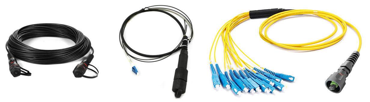
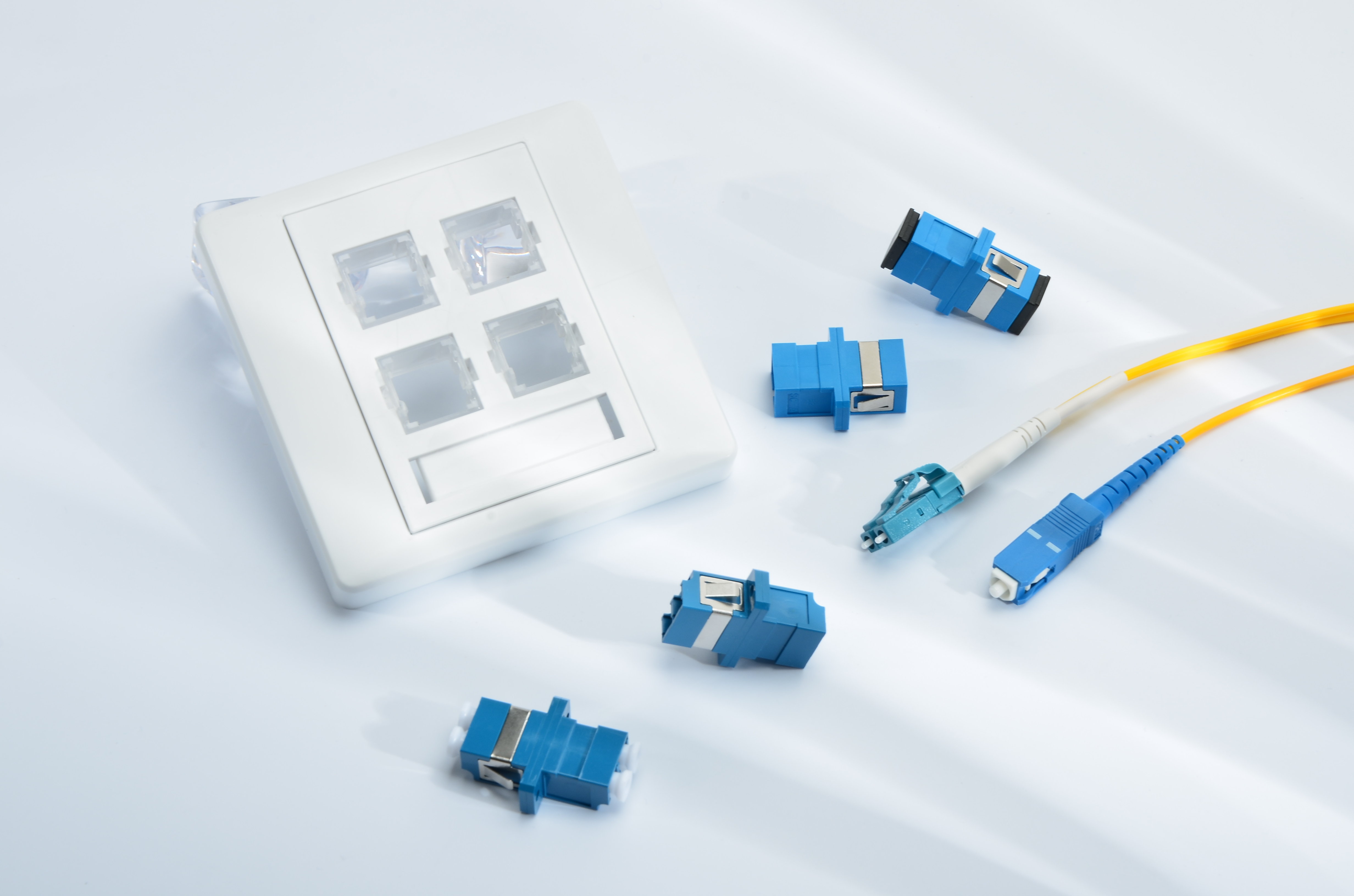
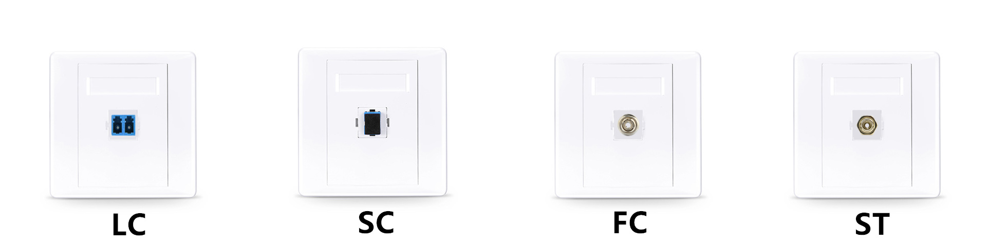
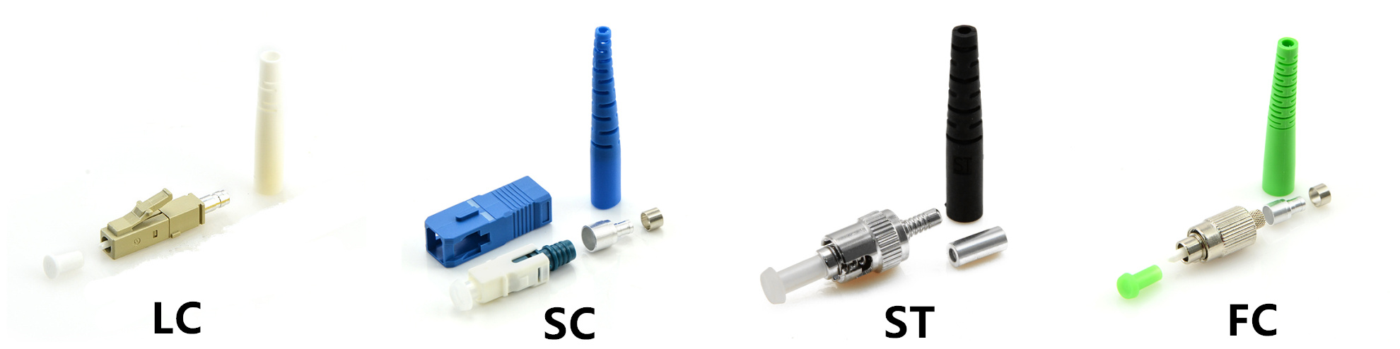
Let’s start from the fiber optic connectors. Choosing the right kind of connector for your termination is extremely important. In today’s market, four types of fiber optic connectors are widely used for terminating single fibers. They are LC, SC, ST and FC connectors. LC connector has a 1.25mm ceramic ferrule which is only half the size of other connectors. It’s a snap-in connector usually used for high-density applications. SC connector uses a 2.5mm ceramic ferrule and also features a snap-in connection for quick cable patching. Different from other connectors, ST connector uses a bayonet twist-lock connection with 2.5mm ferrule. Moreover, FC is a screw type connector with 2.5mm ferrule but is becoming less popular than LC and SC connectors.
common-fiber-optic-connector

Connector Polish Styles
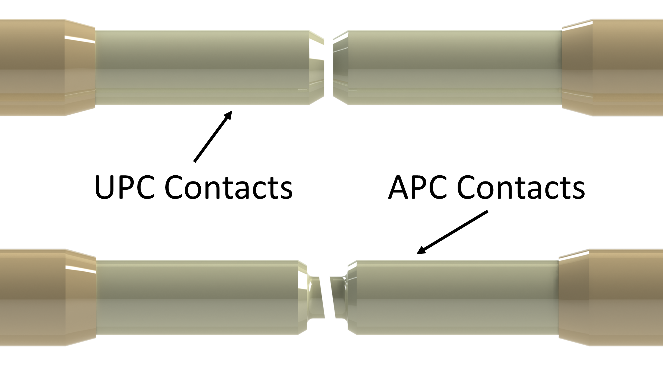
When terminating the optic fiber with connector, you should also decide the polish type if the connector is not polished in advance. Generally, connector end face will be polished to minimize back reflection of light. Using the mated polish styles, light can propagate through connectors with lower fiber loss. There are four types of polish styles - flat, PC, UPC and APC polishes. Among them, UPC and APC types are more popular in the industry. The major difference between UPC and APC connectors is that the APC type is polished at an 8-degree angle while UPC has no angle, but they are both slightly curved for better core alignment. As for the color, UPC connector is usually blue and APC connector is green.
upc-apc-polish

Important Precautions
Fiber optic cable is very fragile and sensitive to contamination, thus we need to pay more attention to the precautions before starting termination. Here lists some general precautions as a reference:
  • Always keep dust cap on unused connectors. Store spare dust caps in a dust free environment.
  • Remember to clean the connector and fiber before termination.
  • Make sure there is no laser light in the fiber during termination process.
  • Do not bend the optic fiber at a radius less than 25 mm.
Termination Process
When everything is ready, we can begin the fiber optic termination. The followings are the specific steps.
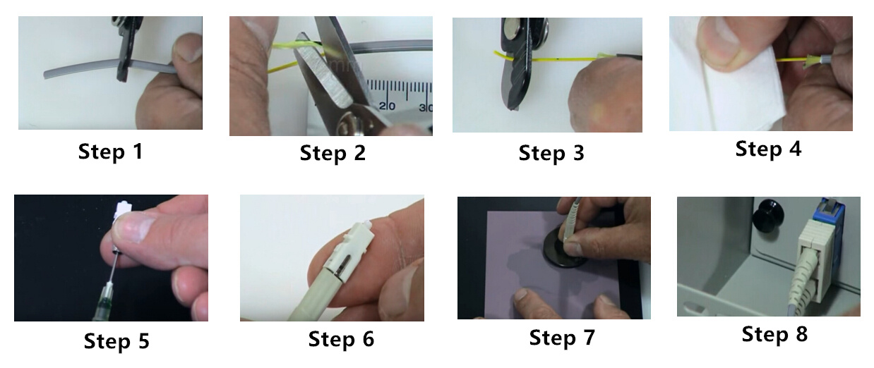
  • Step 1, measure and mark the cable jacket to the desired length(usually 35 mm). Place jacket stripper on mark and squeeze gently until cutter closes. Pull the cut section off the cable.
  • Step 2, measure and mark kevlar to the desired length(usually remain 7 mm). Use scissors to cut away extra kevlar.
  • Step 3, measure and mark the buffer to the desired length(usually remain 16 mm). Strip the buffer in several small lengths to avoid fiber damage.
  • Step 4, use a lint-free, alcohol-soaked tissue to clean the fiber.
  • Step 5, fill the syringe with adhesive, and slowly inject the adhesive into the ceramic tip.
  • Step 6, gently insert the fiber into the connector and put the connector components together.
  • Step 7, place the connector in the polishing disk. Put it on the polishing film, and lightly polish the connector for 8 to 10 times.
  • Step 8, mission complete! Give it a try on your equipment.
fiber-optic-termination
Conclusion
Bare fiber terminated with fiber optic connectors greatly eases the stress for cable installation. It is always recommended to turn to the professionals for help when doing fiber optic termination.

2016年11月27日星期日

How to Organize Cables With J-Hook?

When managing large amount of cables, using a cabling pathway is very useful to provide better support for the cables. Common pathway systems are usually structured with conduits, cable trays, ladder racks, surface raceways, and underfloor ducting systems. Construction materials can be made of steel, aluminum, fiber glass or plastic. However, it is not that necessary to lay every inch of cable on top of a support element. Lots of pathway materials can be saved for other important applications. Is there any solution can both save the construction material and provide continuous support for the cables? The answer is yes. J-hook system perfectly solves the issue with greater flexibility and simpler installation. This article is going to present some basic information about J-hook.

What Is a J-Hook?
The name of J-hook comes from its side view of the letter “J” with a semi-circular bottom section. Cables can be put in the rounded gaps between J-hooks for a continuous support. J-hook is also designed with smooth beveled edges which provides a large bending radius for cables. It is widely used for indoor and outdoor applications providing a speedy and easy installation.
j-hook

Common Attachments of J-Hook
J-hook can be fitted with many kinds of attachments allowing for a more flexible use. The followings are some common fitting types for wall-mount J-hook.
J-Hook With Angle Bracket
Using the 90-degree angle bracket, J-hook can be fastened onto the ceiling. It is also an effective solution for cable trays. This attachment can be easily installed or removed as you want.
J-Hook With Beam Clamp
This attachment can install J-hook to the horizontal flanges with the knock-on beam clamp. It allows for up to 1/8 inch flange thickness. In addition, J-hook with beam clamp is able to rotate 360 degrees to support all directional cable runs.
J-Hook With Hammer-On Clip
Hammer-on clip attachment fitting can be quickly installed with only a hammer. It is also able to swivel 360 degrees for various directional runs of cable.
J-Hook With Wire/Rod Clip
Wire/rod clip is also known as bat wing clip due to its bat shape. It attaches the J-hook to a wide variety of structures. The clip can snap onto the wire that holds up ceiling grids, thus the cable can be suspended at any position in a plenum space.
j-hook-attachment

Steps for J-Hook Installation
  • Step 1, fasten J-hook with the right attachment. It depends on where the J-hook is located. Wall, stud, beam, flange and drop-wire mounting are the common supporting structures.
  • Step 2, align snap lock attachment of J-hook with holes of the chosen bracket and snap J-hook into position.
  • Step 3, lay the cable in J-hooks. The intervals between J-hooks is around 1.2 to 1.5 m.
  • Step 4, look over your installation to ensure the cables are neatly laid on the J-hooks.
Benefits of J-Hook
Compared with traditional pathway elements, J-hook is easier to install and move on-site without the need for special tools. A variety of attachment types enable the flexibility of J-hook to be placed at different locations. There is more headroom capability when using J-hooks. Its wide-base design also maintains the bend radius of large diameter cables.

Conclusion
J-hook is absolutely a simpler solution for horizontal cabling support. Different from other continuous support systems, J-hook system is more economical with fewer logistical demands, less installation labor and reduced material cost. Since it can be used in multiple environments and applications, more and more cabling projects have been adopting J-hook system for construction.

Trend of Cloud Computing in Data Center

In the past, traditional data centers were mainly established by hardware and physical servers. However, the data storage is limited to the physical restriction of space. Network expansion became a headache for IT managers. Gladly, virtualized data center with cloud computing service has emerged and continued to be the trend since 2003. More and more data center technicians adopt it as a cost-effective solution to achieve higher bandwidth performance. This post will help you to have a better understanding of cloud computing in data center.
cloud-computing-of-data-center

What Is Cloud Computing?
Cloud computing service is not restricted to one data center. It may includes multiple data centers scattered around the world. Unlike the traditional data center architecture where the network users owned, maintained, and operated their own network infrastructure, server rooms, data servers, and applications, cloud data center is providing business applications online that are accessed from web browsers, while the software and data are stored on the servers or SAN devices. Thus, applications using cloud-based computing are running on servers instead of local laptop or desktop computer. There is no need for users to know the position of data center and no need for experts to operate or maintain the resources in the cloud. Knowing the way to connect to the resources is enough for the clients.

Advantages of Cloud Computing
Cloud computing brings many great changes for data center networking. Here lists some key benefits of cloud computing.
  • Flexibility - Cloud computing has the ability to update hardware and software quickly to adhere to customer demands and updates in technology.
  • Reliability - Many cloud providers replicate their server environments in multiply data centers around the globe, which accounts for business continuity and disaster recovery.
  • Scalability - Multiply resources load balance peak load capacity and utilization across multiply hardware platforms in different locations.
  • Location and hardware independence - Users can access application from a web browser connected anywhere on the internet.
  • Simple maintenance - Centralized applications are much easier to maintain than their distributed counter parts. All updates and changes are made in one centralized server instead of on each user’s computer.
cloud-computing-advantages

Traditional & Cloud Data Centers Cost Comparison
Cost is always an important concern for data center building. One reason why cloud computing is so popular among data centers is because its cost is much lower than the same service provided by traditional data centers. Generally, the number of cost mainly depends on the size, location and application of a data center.

Traditional data center is more complicated by running a lot of different applications, but this has also increased the workloads and most applications are only used by few employees making it less cost-effective. 42 percent of the money is spent on hardware, software, disaster recovery arrangements, uninterrupted power supplies, and networking, and 58 percent for heating, air conditioning, property and sales taxes, and labor costs. While cloud data center is performing the service in a different way and saves the cost for servers, infrastructure, power and networking. Less money is wasted for extra maintenance and more for cloud computing, which greatly raises the working efficiency.

Is It Secure to Use Cloud Computing?
Data security is always essential to data centers. Centralization of sensitive data in cloud computing service improves security by removing data from the users’ computers. Cloud providers also have the staff resources to maintain all the latest security features to help protect data. Many large providers will safeguard data security in cloud computing by operating multiple data centers with data replicated across facilities.

Conclusion
Cloud computing service has greatly enhanced the high performance of data centers by reducing the need for maintenance and improving the ability of productivity. More data centers are turning into cloud-based these days. It is definitely an efficient way to provide quality data service with cloud technology.

2016年11月20日星期日

Getting to Know Fiber Collimator

Passive optical components are widely used to ensure higher performance of optical networks. There are many kinds of passive optical devices deployed for different applications. Fiber collimator is an important type used for collimating optical light. In this article, we will get to know the basic knowledge of fiber collimator.

What Is Collimated Light?
Before getting to know fiber collimator, we should first understand the meaning of collimated light. Collimated light is the light whose rays are parallel, and therefore will spread minimally as it propagates. A perfectly collimated beam, with no divergence, would not disperse with distance and is sometimes said to be focused at infinity. Hence, a collimated light can travel along the right path to decrease fiber optic loss. However, in actual practice, optical lights may not always transfer in a right direction between different parts, such as from laser diode to fiber, from fiber to planar waveguide, or from micro-optical crystal to fiber, etc. In order to solve the problem, fiber collimator plays an important role in adjusting the light into the desired direction to enable the high performance of fiber optic transmission.
collimated-light

Introduction to Fiber Collimator
A fiber collimator is a device that narrows a beam of particles or waves. It can either cause the directions of light to become more aligned in a specific direction, or cause the spatial cross section of the beam to become smaller. Usually, fiber collimator is required to naturally transform diverging lights from an optical fiber to a parallel beam of light. It consists a single-mode or multimode fiber pigtail and a collimating lens. Collimator can also be used to calibrate other optical devices to check if all elements are aligned on the optical axis.
fiber-collimator

How Does It Work?
When placing the fiber end on the collimator lens, the light will be aligned to a parallel direction. Then through a slight adjustment of fiber end position, the working distance is obtained. The working distance of fiber collimator is related to the distance between fiber end and lens. According to the actual demands, we can determine the parameters of fiber collimator, such as distance between fiber end and lens, beam radius, accuracy, to achieve better performance.
fiber-collimator-working-principle

Lens Types of Fiber Collimator
Nearly all types of lens have been used for fiber collimator. They are the fiber lenses, ball lenses, aspherical lenses, spherical singlets and doublets, GRIN (GRaded INdex) lenses, microscope objectives, cylindrical lenses and so on. Under most circumstances, GRIN lens are widely used because of the low cost and small size. However, when it comes to larger beam diameters, spherical singlet or doublet lenses are more suitable for the application. In addition, lens materials are also different. Glass, plastic and silicon are the common lens materials.

Conclusion
Fiber collimator is an effective passive optical component used for laser beam collimating. This article presents some simple facts about fiber collimator, you can take it as a reference for beginners. Selecting the right type of fiber collimator is essential to the performance of network, you should consider your project requirements as important factors. Moreover, although fiber collimator is a small device, it can still be costly in some situations. Your budget limit should also be taken into consideration. Consulting a professional technician for help is always recommended.

Using IP67 Fiber Cable For Fiber Link Protection

Fiber optic cables have taken a large percentage of today’s network market. Compared with copper cables, optical cables are faster in speed and lighter for carry. The deployment of fiber optic cables has brought many benefits to ordinary people, but the disadvantages of fibers can also be fatal. Optic fibers are easily breakable and polluted by dust, liquid and other contamination. Hence, fiber optic cables should be designed to accommodate to different kinds of environment. IP67 fiber cable is a type of specially used fiber cable with dust-proof and water-proof functions. This post will guide you to know more about this special fiber cable.

Meaning of IP67
When hearing the name of IP67 fiber cable, you may be curious about the meaning of IP67. Actually, “IP” is a kind of rating defined by International Standard IEC 60529. The abbreviation stands for international protection which classifies the degrees of protection provided against the intrusion of solid object (including body parts), dust, accidental contact, and water in electrical enclosures. The IP code consists of two numbers, such as IP67. The first number represents the solid object protection, and the second is the water protection. Following picture presents the category of IP codes. If either number is represented by an “X”, it means the product has not been tested in that category. It does not equate to a ranking of 0, but it also does not guarantee any protection. Therefore, IP67 means that the cable is protected from dust at the highest level and against temporary immersion in water.
ip-rating-code

Construction of IP67 Fiber Cable
IP67 fiber optic patch cable contains the ordinary optic fiber and special IP67 fiber optic connector. IP67 connector is designed based on the conventional connector with a aluminum shell of spring-loaded push-pull locking mechanism. The shell protection can block dust and liquid from the inside connector. The following picture gives a detailed structure of IP67 LC duplex connector.
structure-of-ip76-cable-connector

Types of IP67 Cables
According to the connectors on each ends, IP67 fiber optic cables can be divided into two types. One type is equipped with IP67 connectors on both ends, and another type is terminated with a IP67 connector on one end and common fiber optic connectors on the other end. Fanout IP67 fiber optic cable is also used for high-density connections.
ip67-fiber-cable

Applications
The strong PU jacket and single-mode APC armored structure of IP67 cable provides 1 Gbps data transfer speed in high bandwidth application, which is five times quicker than standard 9/125 μm fiber patch cable. The low insertion loss IP67 cable connector has a simple push-to-latch and a pull-to-release outer sleeve for mating and un-mating action allowing for easier install or uninstall. Designed according to the IEC60603-7 interface standard, the connector can also match with other similar mechanical systems. IP67 cables are often used in FTTH, FTTA, LAN test equipment and military industry deployed at junction cabinets in the street, remote radio head connection, wind mills or direct buried installation.

Conclusion
IP67 fiber optic cable offers great protection for optic fibers against dust and water under severe outer environment. It is wise to use IP67 fiber cables in these places to secure your data links. Inner shell connectors of the cable are now optional with LC, SC, ST and FC types. You may regard IP67 cable as a considerable choice for your network.

source:http://www.fiber-optic-cable-sale.com/using-ip67-fiber-cable-fiber-link-protection.html

2016年11月11日星期五

Fiber Protection Sleeve Secures Your Fusion Splices

Fiber optic splicing, especially fusion splicing, has become increasingly important for OSP (outside plant) deployment. The process is by joining the two fiber ends to create longer cable runs. As we know, spliced bare fibers are fragile to be easily breakable. Therefore, a good protection for the spliced fibers during fiber optic splicing is extremely necessary. Luckily, a small component named fiber protection sleeve perfectly solves the issue. It acts like a strong coat for the fiber splices to prevent unpredictable fractures. This post will take you to understand the basic knowledge about fiber protection sleeve.

Construction of Fiber Protection Sleeve
Generally speaking, a fiber protection sleeve consists three parts. The first part is the inner tube made by hot-meltable adhesive. This material can encapsulates the fusion splice joint and provides vibration damping and an environmental seal so as to protect the fiber from damage and contaminants. The second part is a reinforcing strength member outside the inner tube. The strength member can be made of stainless steel, ceramic or non-metallic. It offers extra rigidity to prevent misalignment, micro bending or breakage of the fiber. The third part is the heat-shrinkable outer tube made of cross-linked polyolefin. This tube provides an instant shrink-force and drives the adhesive liner into all areas of the splice and excludes all the air. The following picture shows the structure of a fiber protection sleeve.
fiber-protection-sleeve-structure

How Does It Work?
When the fibers are melt during the fusion splicing, technician will use the sleeve on the melt point as a protection. Once the hot-meltable adhesive tube touches the melted fiber, it also melts to tightly wrap the fiber joint for the filling and sealing functions. Likewise, when the heat-shrinkable tube is heated, it shrinks to wrap the fiber joint, strength member and hot-meltable tube to form a unity preventing moisture and increasing fiber joint’s strength.

Two Types of Fiber Protection Sleeve
Single Fiber Protection Sleeve
This kind of protection sleeve is used for single fibers. Its strength member adopts the stainless steel needles to reduce fiber damage. Typical lengths are 40 mm and 60 mm. The sleeve color is selective, but most people would choose the transparent tube for better inspection of the fiber status.
single-fiber-protection-sleeve

Ribbon Fiber Protection Sleeve
The ribbon type is to protect ribbon splices of multiple fiber counts. Ceramic strength member is used to support the splices. Fiber counts in a ribbon sleeve vary from 2 to 12 fibers. The length of the sleeve is usually 40 mm. If stronger protection is required, you can choose the ribbon protection sleeves with double ceramic strength members.
ribbon-fiber-protection-sleeve

Be Aware of These Precautions
While utilizing the fiber protection sleeves, there are some important precautions for operators to know. The benefits of the precautions are about avoiding unnecessary loss and securing the fiber for a long-term use.
  • Point 1, do not leave air bubbles in the protection tube. This ensures the long-term reliability of the fiber splices.
  • Point 2, the tension applied to the fiber should be uniform so that the fiber can stay straight in the protective sleeve.
  • Point 3, the tension applied to the fiber should not be too large in case fiber cracks increase.
  • Point 4, try to avoid fiber twisting. Because this may cause micro-bending and unnecessary fiber loss.
  • Point 5, do not release the tension until the heat-shrinkable tube is completely shrunk, cooled and shaped. This can avoid the uneven heating which leads to fiber bending.
Conclusion
Fiber optic protection sleeve is usually used during the process of fiber optic splicing. Although the sleeve is very small, it provides great support for the fiber joint. Single fiber protection sleeve and ribbon fiber protection sleeve are two common types in the market. All the above are available in FS.COM. If you are interested, please visit the website for more information.

2016年11月9日星期三

Have You Used Fiber Optic Wall Plate for FTTx Applications?

Did you notice the square object with jacks installed on the wall before? It is often called as wall plate. There is a variety of wall plates used in everyday life. Almost every room will have one to enable convenient cable deployment inside buildings and houses. As for FTTx applications, fiber optic wall plate is an indispensable component to keep fiber optic link away from dust and damage. This article will mainly give some details about fiber optic wall plate.
fiber-optic-wall-plate

What Is Wall Plate?
First, let’s get to know more about the basics of wall plate. Wall plate, also called as wall outlet, workstation outlet or station outlet, is a flat plastic or metal plate that usually mounts in or on a wall (sometimes may be mounted in floors or ceilings). A wall plate has one or more jacks. A jack refers to the connector outlet employed for physical and electrical connection to the network cabling system. According to different networks, wall plates is divided into two types as fiber optic wall plates and copper wall plates. Since optical network has been leading the world trend, today we will get to know more about fiber optic wall plates.

Types of Fiber Optic Wall Plates
Fiber optic wall plate is designed to establish the connection between two fibers. Based on different adapters, fibers, port counts and port orientations, fiber optic wall plates have many classifications.

Classified by Adapter
There are typically four types of fiber optic connectors used in optical network, therefore the fiber optic adapters installed on the fiber optic wall plates are also different. LC, SC, FC and ST adapters are the common types. When you need to find a matching fiber optic wall plate, just check your fiber connector to see if it is the same type as the wall plate.
adapter-type-of-wall-plate

Classified by Port Count
As for port count of the fiber optic wall plate, a typical wall plate holds up to four ports. For individual homes, sing-port type is mostly used for FTTH network. But for the office buildings, multi-port type is required for FTTD applications. In addition, if other ports are aimed for different applications, the ports can be made as hybrid ports with mixed types of adapters.
port-count-of-wall-plate

Classified by Port Orientation
Port orientation is another way to divide fiber optic wall plates. Using the right orientations can provide fiber links better protection under different environment. Three common types of port orientations are straight, box-shaped and angled.
port-orientation-of-wall-plate

Classified by Fiber
Fiber optic cables are made of different types of fibers. In order to satisfy the demands for all kinds of fiber cable deployment, fiber optic wall plates are also distinguished by single-mode fibers of OS2, and multimode fibers of OM1, OM2, OM3 and OM4. Moreover, single-mode fiber optic wall plate is used for most FTTx projects.

How to Install Wall Plate?
As a reference, here are the recommended steps for installing box-shaped wall plates on the wall:
  • Step 1, determine the location of the new cabling wall plate. Use a pencil to mark a line indicating the location for the top of the wall plate.
  • Step 2, use the hole template to trace the outline of the hole to be cut onto the wall with a pencil. Keep the top of the hole aligned with the mark made in step 1.
  • Step 3, follow the lines and use a drywall keyhole saw to cut out a hole.
  • Step 4, insert the wall plate into the hole. If it won’t fit in, trim the sides of the hole with a razor blade or utility knife.
  • Step 5, secure the wall plate by screwing the box to the drywall or by using the friction tabs.
Conclusion
Fiber optic wall plate is an important part for FTTx applications. Selecting the right one from so many types of wall plates is also a task. All the aspects for your project should be taken into consideration. FS.COM is a place where you can find different types of fiber optic wall plates. You are welcome to get more detailed information in there.

2016年11月4日星期五

Key Components to Form a Structured Cabling System

Building a structured cabling system is instrumental to the high performance of different cable deployments. Typically, a structured cabling system contains the cabling and connectivity products that integrates the voice, data, video, and various management systems (e.g. security alarms, security access, energy system, etc.) of a building. The structured cabling system is based on two standards. One is the ANSI/TIA-568-C.0 of generic telecommunications cabling for customer premises, and another is the ANSI/TIA-568-C.1 of commercial building telecommunications cabling for business infrastructures. These standards define how to design, build, and manage a cabling system that is structured. Six key components are included to form a structured cabling system.

Six Subsystems of a Structured Cabling System
Generally speaking, there are six subsystems of a structured cabling system. Here will introduce them respectively for better understanding.
structured-cabling-system

Horizontal Cabling
The horizontal cabling is all the cabling between telecommunications outlet in a work area and the horizontal cross-connect in the telecommunications closet, including horizontal cable, mechanical terminations, jumpers and patch cords located in the telecommunications room or telecommunications enclosure, multiuser telecommunications outlet assemblies and consolidation points. This type of wiring runs horizontally above ceilings or below floors in a building. In spite of the cable types, the maximum distance allowed between devices is 90 meters. Extra 6 meters is allowed for patch cables at the telecommunication closet and in the work area, but the combined length of these patch cables cannot exceed 10 meters.

Backbone Cabling
Backbone cabling is also known as vertical cabling. It offers the connectivity between telecommunication rooms, equipment rooms, access provider spaces and entrance facilities. The cable runs on the same floor, from floor to floor, and even between buildings. Cable distance depends on the cable type and the connected facilities, but twisted pair cable is limited to 90 meters.

Work Area
Work area refers to space where cable components are used between communication outlets and end-user telecommunications equipment. The cable components often include station equipment (telephones, computers, etc.), patch cables and communication outlets.

Telecommunications Closet (Room & Enclosure)
Telecommunications closet is an enclosed area like a room or a cabinet to house telecommunications equipment, distribution frames, cable terminations and cross connects. Each building should have at least one wiring closet and the size of closet depends on the size of service area.

Equipment Room
Equipment room is the centralized place to house equipment inside building telecommunications systems (servers, switches, etc.) and mechanical terminations of the telecommunications wiring system. Unlike the telecommunications closet, equipment room houses more complex components.

Entrance Facility
Entrance facility encompasses the cables, network demarcation point, connecting hardware, protection devices and other equipment that connect to the access provider or private network cabling. Connections are between outside plant and inside building cabling.

Benefits of Structured Cabling System
Why do you need the structured cabling system? Obviously, there are many benefits for using the system. A structured cabling can standardize your cabling systems with consistency so that the future cabling updates and troubleshooting will be easier to handle. In this way, you are able to avoid reworking the cabling when upgrading to another vendor or model, which prolongs the lifespan of your equipment. All the equipment moves, adds and changes can be simplified with the help of structured cabling. It is a great support for future applications.
structured-cabling

Conclusion
From this article, we can know that a structured cabling system consists of six important components. They are horizontal cabling, backbone cabling, work area, telecommunications closet, equipment room and entrance facility. Once you split the whole system into small categories, the cabling target will be easier to get. As long as you keep good management of these subsystems, your cabling system is a success to be called as structured wiring.

2016年11月2日星期三

Building MDU Network into Brownfield and Greenfield

Multi-dwelling unit (MDU), namely multi-family residential, are the structures of housing where there are more than one living unit per location. MDU classification of housing has been considered as an important growth opportunity for communication services providers according to the population density and economics of scale. Generally speaking, there are two applications for MDU FTTx network deployments as “greenfield” and “brownfield”. This post will introduce the basic information about MDU and its network building applications.

Three Types of MDUs
In North America, MDUs can be classified into three construction versions of high-rise MDU, mid-rise MDU and low-rise MDU. Here will explain them one by one.

High-Rise MDU
This type of MDU refers to the large multi-story building like condo or apartment with more than ten floors and 128 living units using the internal residential entry. High-rise MDU is typically designed as vertical living style and planned for cabling access to the different stories and sections of the building thereby making sure that the FTTP network functions efficiently and reliably over high levels.
high-rise-mdu

Mid-Rise MDU
Mid-rise (medium-rise) MDU is the leased or owned condo or apartment with up to 10 stories including 12 to 128 living units using the internal residential entry. For new mid-rise MDU, its fiber deployment is similar to the high-rise buildings. However, many old mid-rise MDUs are built as walk-ups and without provisions for new cabling networks. It is a challenge for these mid-rise residential buildings to find space for structured cabling.
mid-rise-mdu

Low-Rise MDU
Low-rise MDU is usually known as condo, townhouse or apartment constructed in garden style or horizontal style. There is only up to 3 floors or stories and 12 living units inside the low-rise MDU with external residential entry. The difficulty level for cable deployment also depends on whether the building is newly constructed.
low-rise-mdu

Brownfield and Greenfield Applications
As mentioned above, the oldness and newness of residential buildings will affect the difficulty degree of cable installations. These two types of architectures are also the basic applications for building MDU network. Greenfield means the newly-built housing communities consisting of many separate living units typically joined together in one or several buildings. However, brownfield refers to the MDU that already exists in a typical urban area.

In a Brownfield application, a service provider must deliver fiber into the customer’s premises quickly, efficiently and securely. The ability to connect fibers as they are needed for new subscribers is best served using a simple “plug and play” approach. Thus, the splice storage should provide a demarcation point, such as a fiber demarcation box, equipped with industry standard connectors.
brownfield-deployment

As for greenfield application, a network operator could ideally place the fiber to every living unit during initial construction. Fiber from every unit may then be run back to central closet and spliced as required inside a closure. A box such as the fiber splice box is an optimal and low cost solution.
greenfield-deployment

Fiber Connectivity Methods
In MDU network applications, service providers can use factory-terminated patch cords or fusion-spliced pigtails to connect fibers. Patch cords are efficient connectivity methods because no tools or splices are required in the field to make the termination. Their simple plug and play installation also minimizes the required skills for setting up the connection, which reduces installation time and labor costs.

Fusion-spliced pigtails can alleviate the issues of cable management for massive patch cords and cable waste for long patch cords. However, the fusion splice machine is expensive and specialized training is required. The fusion splicer also requires electrical power in places like MDU hallways where power outlets aren’t readily available.

Conclusion
The building of FTTx network in MDUs has become more and more popular around the world. Project installer should make proper connectivity plan according to different structures of MDUs. The complexity of deployment will also depends on whether the MDU is built in greenfield or brownfield. A successful network deployment in MDU is measured in many ways.