2016年10月28日星期五

Getting to Know Optical Circulator

The utilization of optical circulator starts from the 1990s, and now it has become one of the important elements in advanced optical communication systems. Similar to the function of an electronic circulator, an optical circulator is used to separate optical signals that travel in opposite directions in an optical fiber. Optical circulator has been widely applied to different fields, such as telecom, medical and imaging industries. Are you ready to know more about this optical device? This article will take you to explore the secrets of optical circulator.
optical-circulator

What Is Optical Circulator?
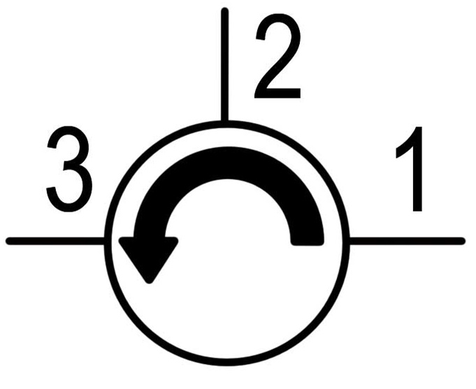
An optical circulator is built to pass light from one optical fiber to another. It is a non-reciprocal device routing the light based upon the direction of light propagation. Both optical circulator and optical isolator can be used to move light forward. However, there is typically more loss of light energy in the optical isolator than in the optical circulator. Optical circulator usually consists three ports: two ports are used as input ports and one port as output port. A signal is transmitted from port 1 to port 2, and another signal is transmitted from port 2 to port 3. Finally a third signal can be transmitted from port 3 to port 1. Many applications only require two, so they can be built to block any light that hits the third port.
optical-circulator-structure

Technologies of Optical Circulator Components
An optical circulator includes the components of Faraday rotator, birefringent crystal, waveplate, and beam displacer. The Faraday rotator uses the Faraday effect, which is a phenomenon that the polarization plane of an electromagnetic (light) wave is rotated in a material under a magnetic field applied parallel to the propagation direction of the lightwave. The light propagation in the birefringent crystal depends on the polarization state of the light beam and the relative orientation of the crystal. The polarization of the beam can be changed or the beam can be split into two beams with orthogonal polarization states. Waveplate and beam displacer are two different forms of birefringent crystal. A waveplate can be made by cutting a birefringent crystal to a particular orientation so that the optic axis of the crystal is in the incident plane and is parallel to the crystal boundary. Beam displacer is used to split an incoming beam into two beams with orthogonal polarization states.

Categories of Optical Circulator
According to polarization, optical circulator can be divided into polarization-dependent optical circulator and polarization-independent optical circulator. The former is used for the light with a particular polarization state, and the latter is not restricted to the polarization state of a light. Most of the optical circulators employed in fiber optic communications are designed to be polarization-independent.

According to functionality, optical circulator can be classified into full circulator and quasi-circulator. As mentioned before, full circulator makes full use of all ports in a complete circle. Light passes through from port 1 to port 2, port 2 to port 3, and port 3 back to port 1. About quasi-circulator, light passes through all ports sequentially but light from the last port is lost and cannot be transmitted back to the first port. For most applications, a quasi-circulator is enough.

Several Applications of Optical Circulator
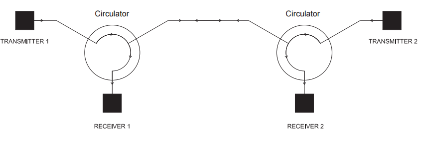
  • Duplex Transmitter/Receiver System: Optical circulators can be used to enable 2-way transmission along a single fiber. Transmitter 1 sends signal through Port 1 of Circulator 1 and through the fiber to Port 2 of Circulator 2 so that it is directed to Receiver 2. The signal from Transmitter 2 follows the opposite path to Receiver 1.
duplex-transmitte-receiver-system

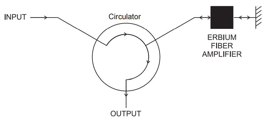
  • Double Pass Erbium Doped Amplifier: This technique allows high gain amplification of a signal through an erbium doped fiber amplifier. The signal passes through optical circulator and optical amplifier, returns from the fiber optic reflector and passes through the amplifier again. This amplified signal is directed through the return port.
double-pass-erbium-doped-amplifier

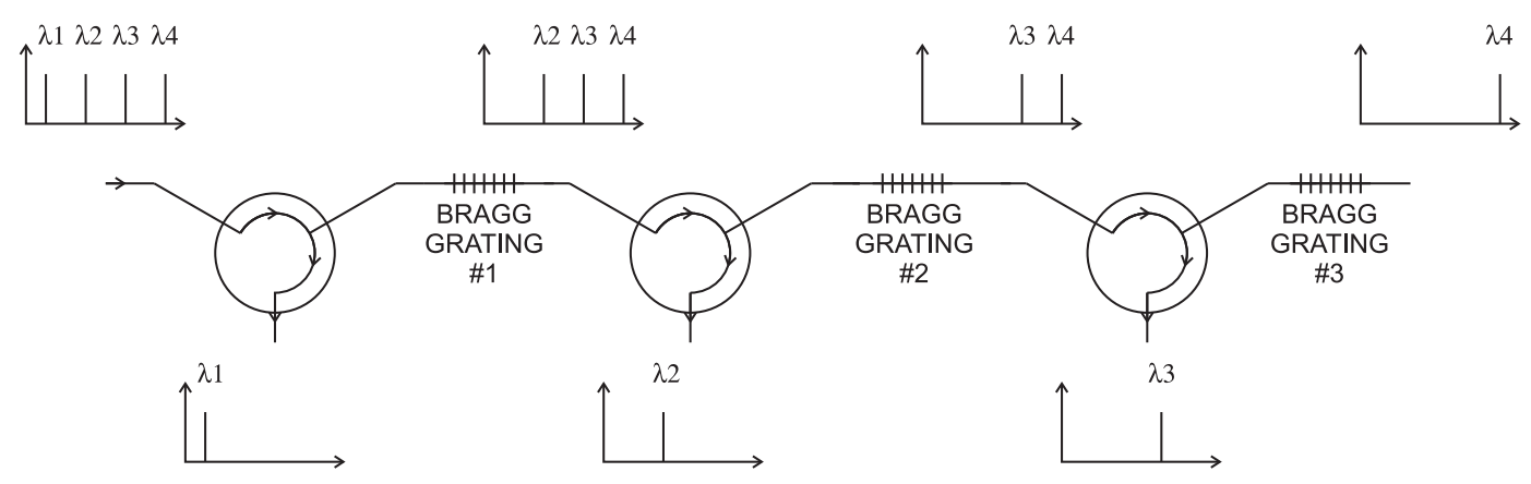
  • Wave Division Multiplexing System: Optical circulators in conjunction with Bragg gratings allow specific wavelengths to be reflected and sent down different paths.
wave-division-multiplexing-system

Conclusion
From this article, you may have a basic impression about optical circulator. It is an efficient and economical solution to use optical circulator for directing light signal with minimum loss. If you are interested in the optical circulator products, welcome to visit fs.com for more information.

An Easy Guide to MPO/MTP Polarity

Nowadays, many data centers are migrating into the 40G and 100G transmission. To prepare for this change, MPO/MTP technology is applied to meet the requirements of high density patching. Typically, a fiber optic link needs two fibers for full duplex communications. Thus the equipment on the link should be connected properly at each end. However, high density connectivity usually requires more than two fibers in a link, which makes it more complex to maintain the correct polarity across a fiber network, especially when using multi-fiber MPO/MTP components for high data rate transmission. Therefore, many technicians would prefer to use pre-terminated MPO/MTP components designed with polarity maintenance for easier installation. This article will specifically guide you to understand the polarity of MPO/MTP products and the common polarization connectivity solutions.

What Is Polarity?
Keeping the right polarity is essential to the network. A transmit signal from any type of active equipment will be directed to the receive port of a second piece of active equipment and vice versa. Polarity is the term used in the TIA-568 standard to explain how to make sure each transmitter is correctly connected to a receiver on the other end of a multi-fiber cable. Once the component is connected to the wrong polarity, the transmission process will be unable to go on.

Structure of MPO/MTP Connector
When discussing about the polarity, MPO/MTP connector is an important component for you to know. An MPO/MTP connector has a key on one side of the connector body. There are two positions of the key - key up or key down. Key up position means that the key sits on top. When the key sits on the bottom, it is the key down position. Moreover, the fiber holes in the connector are numbered in sequence from left to right named as P1 (position 1), P2, etc. Each connector is additionally marked with a white dot on the connector body to designate the P1 side of the connector when it is plugged in. The MPO/MTP connector can be further divided into female connector and male connector. The former has no pins while the latter has two pins on the connector. The following picture shows the basic structure of MPO/MTP connector.
structure-of-mpo-connector

Connecting Methods of A, B, C
The TIA standard defines two types of duplex fiber patch cables terminated with LC or SC connectors to complete an end-to-end fiber duplex connection: A-to-A type patch cable is a cross version and A-to-B type patch cable is a straight-through version. Based on this, there are three polarity connecting methods for MPO/MTP products. Here will introduce them in details.
duplex-patch-cable

Method A is the most straight-forward method. It uses straight-through patch cords (A-to-B) on one end that connect through a cassette (LC-to-MPO or SC-to-MPO depends on what the equipment connector is), a straight-through MPO/MTP key up to key down backbone cable and a “cross-over” patch cord (A-to-A) at the other end.
method-a

Method B is the “cross-over” occurred in the cassette. The keys on the MPO cable connectors are in an up position at both ends, but the fiber that is at connector P1 in one end is in P12 at the opposite end, and the fiber that is in P12 at the originating end is in P1 at the opposing end. Only A-to-B type patch cord is needed for this method.
method-b

Method C is the most complicated. There is pair-wise “cross-over” in the backbone cable. A-to-B patch cords are used on both ends. The cassette uses MPO/MTP key up to key down and the backbone cable is pair-wise flipped so P1, P2 connects to P2, P1 and P3, P4 connects to P4, P3, etc.
method-c

Conclusion
Knowing the polarity of MPO/MTP system helps you better upgrade the 40G and 100G networks. According to different polarity methods, choosing the right MPO/MTP patch cables , connectors and cassettes will provide greater flexibility and reliability for your high density network.

2016年10月21日星期五

How to Understand DDM/DOM Function of SFP Transceiver

When seeing the parameters of SFP transceivers, have you ever been confused about the description of “DDM/DOM support”? Definitely, the SFP transceivers with this supported function are better than those transceivers without such function. What is the real meaning of this parameter and how do we use it to facilitate our work? This article will give you the detailed answers.
sfp-transceiver

What Does DDM/DOM Mean?
DDM refers to Digital Diagnostics Monitoring. It is a technology used in SFP transceivers which gives the end user the ability to monitor real-time parameters of the transceivers. The monitored parameters include optical output power, optical input power, temperature, laser bias current, and transceiver supply voltage etc.

DOM refers to Digital Optical Monitoring. It is also a technology which allows you to monitor important parameters of the transceiver module in real-time. You can use DOM to monitor the TX (transmit) and RX (receive) ports of the module, as well as input/output power, temperature, and voltage. According to these monitored parameters, network technicians are able to check and ensure that the module is functioning well.

Typically, DDM and DOM are similar to each other. They are usually used together to describe the real-time monitoring function of SFP transceivers.

Three Applications of DDM/DOM
Predicting Module Lifespan
This failure prediction enables network managers to find potential link failures before the system performance is affected. Through fault tracing, the network administrator can switch services to the backup link or replace the suspicious device in order to repair the system without interruption. By the real-time monitoring of operating voltage and temperature inside the SFP transceiver, administrators can identify the potential problems. For example, when Vcc voltage is too high, it will cause the breakdown of CMOS device, but when it is too low, the laser will be unable to work.

Locating Fault Position
In an optical link, locating the location of a fault is critical to the rapid loading of service. The fault isolation feature of DDM/DOM allows the system administrator to quickly locate the link failure. It can be used to locate whether the fault is in the module or on the line, and whether the fault is in the local module or in the remote module. By quickly locating the fault, the fault recovery time of the system is greatly reduced.

Verifying Module Compatibility
Another application of DDM/DOM is the verification of module compatibility. Compatibility verification is used to analyze if module's working environment is consistent with the data sheet or compatible with the relevant standards or not. The performance of the module can only be guaranteed in the compatible working environment. Otherwise, the non-compatible environment will cause the decreased performance of transceivers, resulting in transmission error.
ddm-dom-function

How to Use DDM/DOM?
Here are five steps of executing the DDM/DOM commands in SFP transceivers:

Step one, Enable example: Router> enable (Enables the privileged EXEC mode. Enter your password if prompted.)

Step two, Configure terminal example: Router#configure terminal (Enters the global configuration mode.)

Step three, Transceiver type all example: Router (config) #transceiver type all (Enters the transceiver type configuration mode.)

Step four, Monitoring example: Router (config-xcvr-type) #monitoring (Enables monitoring of all optical transceivers.)

Step five, Monitoring interval example: Router (config-xcvr-type) #monitoring interval 500 ((Optional) Specifies the time interval for monitoring optical transceivers. Valid range is 300 to 3600 seconds, and the default value is 600 seconds.)

Conclusion
From this article, you can know that DDM/DOM function assists the network specialists easily find out problems inside fiber links. It simplifies the maintenance work and secures the system’s reliability. We provide many types of SFP transceivers with DDM/DOM function. If you have such requirement for your device, please search at our website for more information.

2016年10月20日星期四

Importance of Using Fiber Color Codes in Data Center

The utilization of color codes in data center effectively helps technicians make better cable management and reduce human errors. Without redundant checking process, people can easily get the information of the device by only one look. Making good use of the color code system can surely save much time during work. This article will mainly present the widely accepted color code system and its important functions.
fiber-color-codes

Introduction to Color Code Systems
Fibers, tubes and ribbons in fiber optic cables are usually marked with different color codes to facilitate identification. There are many color code systems for national or international use. All these systems are characterized by using 12 different colors to identify fibers that are grouped together in a common bundle such as a tube, ribbon, yarn wrapped bundle or other types of bundle.

Different color code standards may be used in different regions. For example, the S12 standard is used for micro cables and nano cables in Sweden and other countries. The Type E standard is defined by Televerket and Ericsson used in Sweden. The FIN2012 standard is used in Finland, etc. However, there is one color code system widely recognized in the world, namely the TIA/EIA-598 standard.

Specifications of TIA/EIA-598 Color Codes
The following picture gives the fiber color coding of TIA/EIA-598 standard. If more than 12 fibers or tubes are to be separated, the color sequence is normally repeated with ring marks or lines on the colored fibers and tubes. As for the fiber cable jacket, orange, yellow, aqua and black color codes are used for their distinction.
color-code-system

Functions of Fiber Color Codes in Data Center
Distinguishing Fiber Grades
As mentioned above, the outer jacket color codes are able to identify the fiber grades. OM1/OM2 cables often adopts the orange jacket, OM3/OM4 cables with aqua jacket, single-mode cables with yellow jacket and hybrid cables (indoor/outdoor cables and outside plant cables) with black jacket. One thing to note is that the mix of OM1 and OM2 or OM3 and OM4 cables may be troublesome. You should make sure not to mingle these cables with the same color code.

Identifying Fiber Patch Cords
Using color codes to label fiber patch cords can reduce the potential for human error. For instance, you may highlight mission-critical patch cords in red, and then teach all technicians that a red patch cord should only be moved with proper authorization or under supervision. Likewise, keeping the fiber connector color consistent with fiber grade color standards will make it simple for technicians to use the right connectors with the cables.

Separating Different Ports
The color-coded port icons can be helpful in identifying different network routings in accordance with internal needs. By tagging each patch panel port, you can simplify and streamline network management.

Differentiating Connector Boots
You can use color codes on connector boots to make routine maintenance and moves, adds and changes easier by helping technicians preserve correct parallel groupings for switch ports. If you change your connector color, you need to ensure that your fiber cable color represents the fiber grade to avoid confusion. You can also change the color of a connector boot to differentiate between different aspects of the network, making it easy for technicians to view the contrast within a panel.

Conclusion
Visual management is more intuitive for specialists to supervise the data center. Color code system has provided an ideal and easy way to solve the cabling problem. Inside the cables, the fiber buffers are also color-coded with standard colors to make connections and splices easier. Therefore, if you are still bothered by these issues of fiber patch cables, using the color code system is a good way to go.

2016年10月18日星期二

Enhance Your Network With 40G QSFP+ AOC

To meet the requirements for higher bandwidth and throughput, 40 Gigabit Ethernet has become a trend for data transmission. A series of 40G equipment are designed to achieve the seamless interconnection in the 40G network. Devices like 40G fiber optic transceivers and 40G direct attach cables are widely used for the high speed transmission. 40G direct attach cables (DAC) are optimal solutions for short range connectivity. It can be further divided into the direct attach copper cable and active optical cable (AOC). This article will focus on presenting you some cost-effective 40G QSFP+ AOC solutions to improve your network.

Basic Knowledge of Active Optical Cable
AOC is a cabling technology that accepts the same electrical inputs as a traditional copper cable, but uses optical fiber “between the connectors”. It adopts electrical-to-optical conversion on the cable ends to improve speed and distance performance of the cable without sacrificing compatibility with standard electrical interfaces. AOC is especially used for short-range multi-lane data communication and interconnect applications. It is made up of the multimode optic fiber, control chip and different connectors with one end terminated with QSFP+ connector and the other end terminated with QSFP+, SFP+, LC or else connectors.
active-optical-cable

Reasons for Choosing 40G QSFP+ AOC
However, why do we often use 40G QSFP+ AOC instead of 40GBASE-SR4 QSFP+ module? In fact, 40G QSFP+ AOC has many benefits that will provoke your interest for choosing it. First is the lower cost compared to the module since the AOC saves the need for extra fiber patch cables. Second is the low insertion and return loss. Although it is used for the same transmission distance, the repeatability and interchangeability performances of 40G AOC are better than 40GBASE-SR4 module. Thirdly, under the four-quadrant test, which is used to test whether the product still keeps better performance even under the lowest and highest voltage and temperature situations, the AOCs are qualified to meet all the demands.

40G QSFP+ AOC Solutions
Here provides some common 40G QSFP+ AOC solutions that are welcome in the market.
Each end of this AOC has a QSFP+ connector used for 40G data propagation. The maximum length can reach up to 100 meters. It is a 40 Gbps parallel active optical cable which transmits error-free parallel 4x10 Gbps data over multimode fiber (MMF) ribbon cables.
40g-qsfp-qsfp-aoc
QSFP+ to 4x SFP+ AOC is a breakout cable offering the professionals a cost-effective interconnect solution for merging 40G QSFP+ and 10G SFP+ between devices of adapters, switches and servers. Users can install this AOC between an available QSFP+ port on their 40Gbps rated switch and feed up to four upstream 10G SFP+ enabled switches.
40g-qsfp-4sfp-aoc
This is also a breakout AOC with a QSFP+ connector on one end and 8xLC connectors on the other. It is a high performance, low power consumption, long reach interconnect solution supporting the 40G Ethernet compliant with the QSFP+ MSA and IEEE P802.3ba 40GBASE-SR4. It is an assembly of 4 full-duplex lanes. Each lane is able to transmit up to 10 Gbps data rate providing an aggregated rate of 40 Gbps.
40g-qsfp-8lc-aoc

Conclusion
Along with the popularity of 40G Ethernet, the market of 40G QSFP+ AOC has been growing over the years. It is definitely a better choice for high speed transmission over short distances. Additionally, if you are looking for higher bandwidth AOCs, there are also 100G QSFP28 AOC and 120G CXP AOC suitable for your needs.

2016年10月14日星期五

How to DIY Ethernet Cables?

Buying the Ethernet cables in stores is probably a common way for average people. However, have you ever met the problem that the cable length is too long or too short? It is so difficult to find the most appropriate cable length at ordinary stores for your network. Especially when the cable is too long, the extra length may end up becoming a mess at your place. In order to solve this issue, why not make your own Ethernet cables? You can create your desired length and the procedures are fairly simple. This post will guide you to make a DIY Ethernet cable.

Essential Tools and Materials
Before you get started, there are some necessary tools and materials needed during the procedure. Wire cutter or wire stripper is used for the task of cutting and stripping wires. RJ45 cable crimping tool can make your cable’s data plug a permanent part of your new cable. RJ45 data plugs are important materials which can be found at many cable stores. Some plugs are labeled specifically Cat 6 or Cat 5e, you can buy specific ones if your network needs one or the other. And you should prepare the bulk Cat 5, Cat 5e, Cat 6 or other Ethernet cables according to your needs. Sometimes, having a cable tester is better since it will save time and prevent headaches down the line when you have a problem with a cable or connection.

Which Wiring Schemes?
Ethernet cables have several standard wiring schemes. T568A and T568B are the common wiring schemes which define the order of the individual wires and pin-outs for eight-pin modular connectors and jacks. If the cable is used for home-networking connections, T568B wiring scheme is recommended. T568A wiring scheme may be employed for the preexisting residential network wiring or other similar projects. The following figure presents the different wiring orders of T568A and T568B.
t568a-t568b-wiring-schemes

Ethernet Cable DIY Steps
After all the preparations, now you are ready to make your own Ethernet cable. Follow these steps and you will soon have your first self-made cable.
  • Step 1, measure the cable to the proper length you want. And don’t forget to add an inch or two because you may lose a bit of cable during the process. Then use the tool to cut down the cable.
cut-the-ethernet-cable
  • Step 2, remove the outer jacket of the cable. A good way to do so is to cut lengthwise with snips or a knife along the side of the cable, away from yourself, about an inch toward the open end. Also leave an inch to an inch and a half if you are green hand.
strip-the-cable-jacket
  • Step 3, untwist and straighten the wires, then arrange the wires into the desired scheme order.
wire-the-cable-into-specific-order
  • Step 4, once your wires are in the correct order, trim the excess away. Only leave slightly less wire to be fit inside the RJ45 clip. And hold the wires in place with your fingers and insert them all at once into the data plug.
install-cable-into-plug
  • Step 5, place your data plug into your crimping tool and give it a firm squeeze. And you just finally complete your Ethernet cable.
cimp-data-plug
Conclusion
If condition permits, using the cable tester to test the Ethernet cable before installation is recommended. Getting this new skill, you will no more worry about the cable length, you can make them as long or as short as you want. Enjoy using your DIY Ethernet cable!

How to Install Aerial Fiber Optic Cables?

When you walk on the street, have you noticed at the fiber cables hanging on the poles overhead? These cables are commonly called as aerial fiber cables, which are widely used for outside plant (OSP) installation on poles. Aerial fiber cables are designed to accommodate the severe environment preventing the destruction of the nature and man-made damage or theft. There are also different types of aerial fiber optic cables. This article will describe the common installation ways and things to notice during installation.
aerial-fiber-optic-cable

Types of Aerial Optical Cables
Aerial fiber optic cables can be classified into the catenary wire style and the self-supporting style according to different installing ways. The catenary wire style refers to the general outdoor loose tube cables which can be lashed into a messenger. The self-supporting style refers to the ADSS (all-dielectric self-supporting) cables. They are made to support their own weight and environmental conditions such as wind and ice. Figure 8 self-supporting aerial fiber optic cables are the common ADSS cables designed for easy and economical one-step installation over long haul network communication.

Aerial Cable Installation Guides
Before Installation
  • Point 1, before the aerial cable installations, making a proper plan is very necessary. All the parties including utilities, street department and so on should be present in the cable route survey. And the plan should be approved by all the parties.
  • Point 2, sufficient clearances must be maintained between fiber optic cables and electrical power cables on joint-use poles.
  • Point 3, existing dead-end pole must be evaluated to see whether they can withstand the stresses during aerial cable installation. You have to evaluate whether temporary guying is needed in order to relieve the temporary unbalanced loading during cable installation.
  • Point 4, splice locations are usually selected during the cable route survey. They are chosen to allow for the longest possible continuous cable spans and a minimum number of splices. They should be easily accessible to a splicing vehicle.
  • Point 5, remember aerial installation should never be done in wet conditions. And make sure all personnel are properly trained for pole line work.
Installation Methods
According to different aerial cable types, there are generally two installation ways. First is to lash a fiber optic cable to a steel messenger. A steel messenger is first installed between the poles. Then a cable reel trailer and truck are used to pull the cable along the messenger. A cable guide and cable lasher are used to wrap around both the messenger and the fiber cable to secure the fiber cable to the messenger. Following the cable lasher is an aerial bucket truck which makes necessary adjustments. At each pole, the fiber optic cable forms an expansion loop to allow for expansion of the messenger. The expansion loop's sizes have both a length and a depth, and its length should be larger than twice its depth. The fiber cable should also maintain its minimum bending radius at all times.
Another way is the direct installation of self-supporting figure 8 aerial cables. It greatly simplifies the task of placing fiber optic cables onto an aerial plant. The self-supporting figure 8 cable incorporates both a steel messenger and the fiber cable into a single jacket of figure 8 cross section. The combination of strand and optical fiber into a single cable allows rapid one-step installation and results in a more durable aerial plant.

During Installation
You should watch out for your safety during cable installation. Here are some tips for you to follow:
  • Tip 1, ensure that the tools and equipment used for the cable installation are in proper working order. Improperly functioning equipment may damage cables or cause injury to personnel.
  • Tip 2, be careful when working near electrical hazards if electric lines are passing through or near the right-of-way where installation is being performed.
  • Tip 3, before pulling cable directly from a figure 8 configuration, make sure that the area inside the loop of the cable is clear of personnel and equipment. Failure to do so may result in injury to the personnel or damage to the cable.
aerial-cable-installation

Conclusion
Installing cables is not an easy thing, especially for aerial cable installations. Extra concentration and patience are needed during the installation. The actual situation is usually much more complex than we talked right here. You need to adjust your plans according to real conditions.

40G QSFP+ Fiber Optic Transceiver Selection Guide

Demand for higher bandwidth has never stopped. Along with the IEEE 802.3ba 40Gbps Ethernet standard published in 2010, 40G QSFP+ (Quad Small Form-factor Pluggable) fiber optic transceivers have been designed to solve the issues during 40G migration. Today, many kinds of 40G QSFP+ modules are widely applied to data centers. However, do you know which one is most suitable for your network? Don’t panic, this article will guide you to know the basic considerations for 40G QSFP+ transceivers selection.
Common 40G QSFP+ Transceiver Types
Here are some ordinary 40G QSFP+ types. Let’s have a look at their differences:
  • 40GBASE-SR4
It reaches 40 Gbps Ethernet over four short-range multimode fiber optic cables and supports link lengths of 100m and 150m respectively on laser-optimized OM3 and OM4 multimode fiber cables. Because of the 850nm vertical-cavity surface-emitting laser (VCSEL) modulation limits, the multimode fiber uses parallel-optics transmission instead of serial transmission. Parallel-optics transmission uses a parallel optical interface where data is simultaneously transmitted and received over multiple fibers and the interfaces are 4x10G channels on four fibers per direction.
40gbase-sr4
  • 40GBASE-LR4
It reaches 40-Gbps Ethernet over four wavelengths carried by a single long-distance single-mode fiber optic cable and supports link lengths of up to 10 km over single-mode fiber with duplex LC connectors. It operates at a wavelength of 1310 nm. The 40 Gigabit Ethernet signal is carried over four wavelengths with 10G on each wave. Multiplexing and demultiplexing of the four wavelengths are managed within the device. It is designed to use in switches, routers and data center equipment where it provides higher density and lower cost when compared with standard SFP+ modules.
40gbase-lr4
  • 40GBASE-CR4
It is a direct attach cable segment with the QSFP+ modules attached to each end of the cable. It reaches 40-Gbps Ethernet over four short-range twinaxial copper cables bundled as a single cable and supports link lengths of up to 10 km over a standard pair of G.652 single-mode fiber with duplex LC connectors. The QSFP+ modules are plugged into the QSFP+ ports on the switch or computer interface. Before you choose to use the 40GBASE-CR4 , please make sure the QSFP+ modules on the cable support the QSFP+ port on your switch or computer interface.
Aspects to Consider During Selection
Cable Type
Cables used with fiber optic transceivers should be matched with each other. As for 40G QSFP+ transceivers, 40GBASE-LR4 can be used with single-mode fiber cables for long distance transmission. And 40GBASE-SR4 is recommended to be used with OM3 or OM4 in short distance with lower insertion loss and higher bandwidth.
Connector Type
From the interface of 40G QSFP+ transceiver, we can know the right connector type. Usually, 40G QSFP+ modules uses the MTP (a high performance MPO connector) and LC connectors. But some special transceivers such as 40GBASE-PLR4 and 40GBASE-PLRL4 will use the MPO interfaces.
Transmission Distance
Just like the common transceivers, 40G QSFP+ modules have different transmission range, such as 100m, 150m, 300m, 1km, 2km, etc. You can decide your transceiver type according to the transmission distance you need.
Wavelength
Wavelength is also an important aspect to consider which 40G QSFP+ transceiver to choose. For example, 40GBASE-SR4 transmit and receive channels in the 832nm to 918nm wavelength range. Make sure the transceiver is working at the right wavelength for your network.
Conclusion
Certainly, many other parameters should also be considered as selection basis. If you are not sure which type to choose, better ask the professionals for help. In order to achieve a high speed network, 40G QSFP+ modules are the necessary solutions. The right selection will contribute a lot to your network transmission.

2016年10月6日星期四

Applications of 3G-SDI Video SFP

At the data rate of 3 Gbps, using HD-SDI (high-definition serial digital interface) fiber converter may cause problems for video displaying, such as splash screen, black or blue screen and lagging frame. Is there any good solution to solve this problem? Definitely, 3G-SDI video SFP (small form-factor pluggable) transceiver is designed to meet the relevant demands. This article will guide you to know the basic information about 3G-SDI video SFP and its common applications.

What Is 3G-SDI?
With the wide deployment of fiber optics, the HD (high-definition) video transmission over fiber is no longer a dream. We are familiar with the HD video interface such as HDMI (high-definition multimedia interface), HD-SDI, HD-CVI (high-definition composite video interface) and so on. But what is 3G-SDI?

3G-SDI is an updated version of HD-SDI which can offer nominal data rates of 1.485 Gbit/s (dual link) and 2.970 Gbit/s serial link, respectively. 3G-SDI system can support the digital video signals with SMPTE424M, SMPTE292M, SMPTE259M, SMPTE297M , SMPTE305M and SMPTE310M standards, as well as the DVB-ASI (EN50083-9) format digital video signals. Similar with HD-SDI, 3G-SDI is generally used for the television broadcasting. But as the technology advances, it is now widely applied in global security applications such as high-end surveillance or unmanned systems, allowing simple designs or upgrades with full HD cameras.

3G-SDI Video SFP & Related Products
A variety of 3G-SDI video products have been launched in the market. These equipment include 3G-SDI extenders, 3G-SDI distribution amplifiers, 3G-SDI matrix switchers and so on. They are adopted with 3G pathological signal but can also be compatible with 1.5G pathological signal for long-distance transmission, meeting the diversified demands of users.

However, though there are many 3G-SDI equipment in the market, most of the products cannot pass the SDI pathological-code test. In this case, if the video signals are transmitted in an irregular bitrate, the issues that are mentioned in the beginning of the article may occur. This phenomenon will happen especially under the operation of 3Gbps (i.e., 1080p application) rather than 1.5G (720p or 1080i application). Why? Excluding the factors of equipment quality and brand differences, the cost factor may be the main reason. In the current market, most of the HD-SDI converters employ the ordinary SFP optics, namely the 1.25G or 2.5G digital SFP to replace the specific video SFP. Inevitably, the error rate increases when transmission bit rate is irregular. Since the application field of HD-SDI converter requires higher quality frames, it is very necessary to use the specific 3G-SDI video SFP to avoid these problems and ensure the high definition and smooth frames of the video.

3G-SDI module is designed in SFP package which is compliant with SFP Multi-Source Agreement (MSA) and SFF-8472. 3G-SDI module can be designed with different form factor such as dual or single transmitter, dual or single receiver, duplex or BiDi (bi-directional) transceiver (transceiver & receiver). According to the operation wavelengths, 3G-SDI module can be used in multimode or single-mode application—works on 850nm wavelength to support up to 300m transmission distance over multimode fiber and 1310 or 1550nm wavelengths to support 10km or 80km transmission distance over single-mode fiber. In addition, 3G-SID CWDM SFP modules are also available in the market. Furthermore, 3G-SDI SFP module also support DDM (digital diagnostic monitoring) function to monitor extensive output optical power, bias current, supply voltage and operating temperature etc.
3G-SDI Video SFP Application Cases
Similar to the ordinary SFP module that is used in the switch to transmit and receive the signals, 3G-SDI SFP module is for the same purpose but used in the HD-SDI equipment. It plays an important role in the application of digital video extension over fiber. Three classical 3G-SDI SFP application cases (over SMF) are shown in the following:

Case 1: Using a 3G-SDI SFP transmitter for transmitting the signals and a 3G-SDI SFP receiver for receiving the signals over a simplex SMF. This is the most basic case of the HD-SDI video transmission.
case1-3g-sdi-tx-rx-1024x611

Case 2: Using 3G-SDI SFP transceivers which can both transmit and receive over a duplex LC SMF.
case2-3g-sdi-sfp-transceiver-1024x611

Case 3: Using a pairs of 3G-SDI BiDi SFP transceiver which can both transmit and receive over a simplex LC SMF. This solution can help save more cost on fiber.
case3-3g-sdi-bidi-1024x611

Conclusion
3G-SDI SFP transceiver is a cost-effective solution for transmitting and receiving high-definition video signals. Our website provides a series of 3G-SDI SFP covering the wavelengths of 850 nm, 1310 nm, 1550 nm, CWDM band, BiDi 1310/1490 nm and BiDi 1310/1550 nm. Each one is tested to be fully compatible with Cisco, Arista, Juniper, Dell, Brocade and other brands.